
Key Takeaways
- Radius determines process selection. CNC tube bending achieves tight radii from 1.5x to 3x the tube’s outer diameter. Tube rolling starts at 10x OD and larger—choose based on your design’s curve requirements.
- Geometry complexity favors bending. RDB produces multi-plane, compound-angle parts. Rolling is limited to single-plane arcs and coils. Complex 3D assemblies require tube bending.
- Material deformation patterns differ. Bending concentrates stress at the bend point, risking wall thinning and ovality. Rolling distributes deformation gradually, preserving wall thickness consistency across long arcs.
- Tolerance requirements narrow options. Aerospace and precision applications demanding ±0.005 inch tolerances require CNC tube bending. Rolling cannot consistently meet tight dimensional specifications.
- Wall thickness guides equipment choice. Thin-walled tubes need mandrel bending to prevent collapse. Thick-walled materials and large profiles suit rolling where RDB forces become prohibitive.
Tube bending and tube rolling both form curves in tubular stock, but they serve different purposes. Tube bending creates tight-radius, precision bends for hydraulic lines, exhaust systems, and structural chassis. Tube rolling produces large-radius sweeps for architectural elements, pressure vessels, and industrial piping. Choosing the wrong process leads to failed parts, wasted material, and missed tolerances.
This guide compares CNC tube bending and tube rolling across process mechanics, application suitability, and limitations. Engineers and fabricators will learn when each method applies, how material deformation differs between processes, and which factors drive process selection for tube fabrication projects.
What Is Tube Bending and How Does the Tube Fabrication Process Work?
Tube bending is a metal forming process that creates precise angles and curves in tubular stock. The tube fabrication process combines CNC tube bending with laser tube cutting, welding, and finishing operations to produce components for automotive, aerospace, HVAC, and industrial applications.
How Does CNC Tube Bending Control Radius, Angle, and Material Deformation?
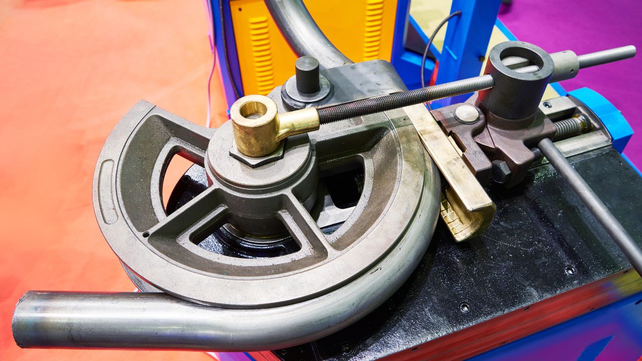
CNC tube bending controls radius, angle, and material deformation through rotary draw bending (RDB). RDB clamps the tube and draws it around a rotating bend die while a pressure die maintains shape. This method achieves a Center Line Radius (CLR) as tight as 1.5 to 3 times the tube’s outer diameter—making it the preferred process for tight, precise bends in single-plane or complex multi-plane geometries.
Bend severity is quantified by CLR, the radius measured to the tube’s centerline. A 3D CLR (three times the OD) is standard. Tighter 2.5D bends require specialized equipment and depend on wall thickness and material ductility. Springback—the material’s tendency to partially return to its original shape—must be compensated for in programming. Stainless steel exhibits higher springback than carbon steel, requiring greater overbend allowances.
What Role Do Mandrels, Dies, and Tooling Play in Tube Bending Accuracy?
Mandrels, dies, and tooling prevent defects and maintain cross-sectional integrity. For thin-walled tubes or tight radii under 2x the tube diameter, a mandrel inserts into the tube to prevent collapse. A wiper die eliminates wrinkling on the inside radius. Each combination of tube diameter, wall thickness, and bend radius demands a specific die set—driving high tooling costs compared to tube rolling.
Industry tolerances limit ovality to 10% of tube diameter and wall thinning to 15% of nominal thickness. Exceeding these thresholds compromises structural performance. Proper tooling selection is the primary factor in meeting these specifications consistently.
How Does Tube Bending Integrate with Laser Tube Cutting and Downstream Fabrication?
Tube bending integrates with laser tube cutting through CAD-driven workflow. Design engineers define the CLR and Degree of Bend (DOB) for every curve using software like Bend-Tech PRO or TubeWorks integrated with SOLIDWORKS. These parameters drive tooling selection and machine setup. The resulting Bill of Materials and fabrication drawings govern the entire production run.
Cutting operations use high-speed saws, laser cutters, or plasma cutters to achieve exact lengths before bending. Deburring follows as a mandatory secondary operation, removing sharp edges and preparing tube ends for welding or coating. This sequence—cut, deburr, bend, weld—defines the standard tube fabrication process flow.
What Is Tube Rolling and How Is the Rolling Process Performed?
Tube rolling is a metal forming process that creates large-radius curves, arcs, and coils by feeding material through a series of rollers. Unlike CNC tube bending, rolling produces sweeping curves rather than tight angular bends—making it suited for architectural elements, pressure vessels, and large-diameter pipe runs.
How Does Tube Rolling Form Large Radii Through Progressive Deformation?
Tube rolling forms large radii through progressive, distributed material deformation. The tube feeds gradually through the rolls, bending incrementally with each pass. This contrasts sharply with rotary draw bending, where deformation concentrates at a single point.
The minimum achievable radius is approximately one times the material thickness. The maximum radius is virtually unlimited—constrained only by machine capacity. This range makes rolling ideal for gentle curves, full circles, and helical coils where tight bends are unnecessary.
What Equipment Configurations Are Used in Tube Rolling Operations?
Roll benders typically use a three-roll pyramid configuration. Two bottom rolls support the tube while an adjustable top roll applies downward pressure to create curvature. This general-purpose setup handles multiple tube sizes and radii without dedicated tooling for each specification—resulting in significantly lower tooling costs than RDB.
Rolling can be performed cold or hot. Cold rolling occurs at ambient temperature and preserves surface finish. Hot rolling heats material above its recrystallization point—exceeding 1,000°F for steel—allowing greater deformation with less force and reduced springback. Hot processes suit thick-walled or high-strength materials that resist cold forming.
How Does Rolling Affect Wall Thickness and Cross-Section Consistency?
Rolling produces less localized wall thinning and ovality than rotary draw bending, especially at large CLR/OD ratios. The gradual deformation distributes stress over a longer tube section rather than concentrating it at a single bend point. This is a key advantage in the tube bending vs. tube rolling process comparison for applications prioritizing material integrity.
However, limitations of rolling include trade-offs between process temperature and precision. Hot rolling yields rougher surface finishes and less dimensional control than cold working. Cold rolling delivers superior mechanical properties and surface quality. High-purity applications demand surface roughness (Ra) of ≤ 0.8 μm—typically achievable only through cold processes with proper equipment.
How Do Tube-Bending and Tube-Rolling Differ in Process, Application Scope, and Inherent Limitations?
Tube bending and tube rolling serve different fabrication needs. The tube bending vs. tube rolling process comparison comes down to bend radius, part complexity, and acceptable material deformation. Understanding these differences guides correct process selection.
How Does the Process Comparison Differ Between Bending and Rolling Mechanics?
The process comparison differs primarily in achievable radius and geometric complexity. RDB achieves tight radii from 1.5x to 3x the tube’s outer diameter. Rolling starts where bending becomes impractical—typically 10x OD and larger. RDB produces complex multi-plane geometries with precise angles like 90° bends. Rolling produces single-plane arcs, coils, and rings.
Production characteristics also diverge. CNC tube bending offers excellent repeatability for mass production of identical parts. Rolling has slower cycle times per part but excels at continuous long-arc production. Choose based on volume requirements and geometric complexity.
How Do Application Suitability and Design Freedom Compare Between the Two Methods?
Application suitability depends on part geometry and precision requirements. RDB is essential for hydraulic lines, exhaust headers, and structural chassis members—components requiring tight radii and exact angles. Rolling suits architectural elements, heat exchangers, and large-diameter pipe runs where sweeping curves define the design.
Design freedom splits along dimensional lines. RDB handles intricate 3D parts with bends in multiple planes. Rolling is limited to 2D curves in a single plane. If the design requires compound bends or tight turns, bending is the only viable option.
How Do Material Deformation and Accuracy Limits Differ by Process?
Material deformation patterns differ significantly between processes. RDB concentrates stress at the bend point, creating high localized wall thinning at the extrados and elevated ovality risk. Rolling distributes deformation gradually over the tube length, minimizing both defects. For applications where material integrity outweighs tight-radius requirements, rolling preserves cross-sectional consistency.
Material waste follows opposite patterns. RDB requires straight sections for clamping, increasing scrap. Rolling accepts continuous feed, reducing waste on long-arc production. These limitations of rolling and bending should factor into cost analysis alongside tooling investment and cycle time.
When Is Tube Bending the More Suitable Manufacturing Method?
Tube bending is the more suitable method when designs require tight radii, multi-axis geometry, or close tolerances. Applications in aerospace, motorsports, and hydraulic systems demand the precision that only CNC tube bending delivers.
Which Applications Require Tight Radii, Multi-Axis Geometry, or Close Tolerances?
Aerospace, motorsports, and hydraulic applications require tight radii and close tolerances. Aerospace tube assemblies demand tolerances of ±0.005 inch or tighter on bend angles, plane of bend, and end-to-end length. Hydraulic system assemblies must contain pressures from 3,000 to 5,000 psi—requiring precise wall thickness control that only mandrel bending provides.
Motorsports fabrication follows similar principles. NHRA regulations permit 1.75-inch OD tubing with 0.083-inch wall thickness for 4130 Chromoly versus 0.118-inch wall for mild steel DOM. Mandrel bending prevents wall collapse and wrinkling that would compromise structural integrity and violate competition rules. These application suitability requirements eliminate rolling as an option.
How Does CNC Tube Bending Support Repeatability in Complex Assemblies?
CNC tube bending supports repeatability through multi-axis control and automated springback compensation. Sophisticated CNC benders produce identical parts across production runs—critical for assemblies where components must interchange without fitting adjustments.
Quality systems validate this repeatability. Automated orbital welding achieves defect rates under 2%. NDT acceptance criteria require 95% statistical confidence levels for inspection reliability. Aerospace First Article Inspection via AS9102 formally verifies that the first production part meets all engineering requirements before full production begins.
When Does Tube Bending Reduce Downstream Fabrication Steps?
Tube bending reduces downstream steps by producing tight-radius bends in a single operation. This eliminates multiple-segment welded assemblies—reducing weld count, inspection time, and potential failure points. Fewer welds means faster production and higher structural integrity.
Material selection amplifies these benefits. Switching from DOM steel to 4130 Chromoly yields 15-20% weight reduction in motorsports roll cage structures due to thinner wall requirements enabled by the stronger alloy. TIG welding remains the industry standard for steel tubing, delivering precise heat input control for high-quality joints on bent assemblies.
When Is Tube Rolling the Better Option for Fabrication?
Tube rolling is the better option when designs call for large-radius curves, sweeping arcs, or continuous coils. The process suits architectural, structural, and industrial applications where gentle curves define the geometry.
Which Applications Favor Large-Radius Curves Over Tight Bends?
Applications favor rolling when bend radius exceeds 10x the tube’s outer diameter. Architectural handrails, curved structural steel, pressure vessel shells, and large-diameter pipe runs all benefit from roll bending’s capability to produce smooth, continuous arcs.
Rolling handles thicker-walled materials and larger profiles where forces required for RDB would be prohibitive. The process is highly efficient for continuous long-arc production—feeding material through the rolls in a single pass rather than setting up individual bends. This efficiency advantage grows with arc length.
When Does Rolling Minimize Localized Stress and Surface Distortion?
Rolling minimizes stress and distortion through gradual, distributed deformation. Unlike RDB’s concentrated bend point, rolling spreads material deformation over the entire arc length. This reduces localized stress concentrations that can cause fatigue failures in service.
The process excels when preserving wall thickness consistency takes priority over tight tolerances. Rolling is also more material-efficient for long arcs due to continuous feed capability—no straight clamping sections required. When material deformation must stay minimal across extended curves, rolling outperforms bending.
How Do the Limitations of Rolling Affect Precision-Critical Designs?
The limitations of rolling restrict its use in precision-critical designs. Rolling is inherently slower for producing single, short-radius bends where RDB completes the operation in seconds. Cycle time per part favors bending for high-volume production of compact components.
Geometric constraints pose larger barriers. Rolling is limited to single-plane curves and cannot achieve complex multi-plane geometries. Hot rolling—necessary for thick or high-strength materials—sacrifices surface finish quality and dimensional precision compared to cold CNC tube bending. Designs requiring tight tolerances, compound angles, or superior surface quality must use bending regardless of radius.
How Should Engineers Choose Between Tube Bending and Tube Rolling?
Engineers should choose between tube bending and tube rolling based on tolerance requirements, material characteristics, and total project economics. The tube bending vs. tube rolling process comparison requires evaluating technical constraints alongside cost factors.
How Do Tolerance Requirements Influence Application Suitability?
Tolerance requirements often determine application suitability before other factors enter consideration. Aerospace critical tolerances of ±0.005 inch favor RDB processes—rolling cannot consistently achieve this precision. Dimensional verification at these tolerances requires Coordinate Measuring Machines (CMMs) and laser scanners to confirm conformance.
Documentation requirements add another layer. Aerospace material traceability demands cradle-to-grave documentation linking every finished part to its original raw material melt. This level of process control aligns with CNC tube bending’s programmable repeatability rather than rolling’s more variable output.
How Should Material Type and Wall Thickness Guide Process Selection?
Material type and wall thickness directly guide process selection. Thin-walled tubes require RDB with mandrel support to prevent collapse during forming. Thick-walled tubes and large profiles suit rolling processes where RDB forces become prohibitive.
Alloy selection interacts with these constraints. Titanium Grade 9 (Ti-3Al-2.5V) is favored for tubing due to superior formability and cold-working capability. Inconel 718 serves high-temperature applications requiring hot corrosion resistance. Titanium’s density of 4.51 g/cm³ versus steel’s 7.85 g/cm³ delivers substantial weight reduction for aerospace and motorsports—but these alloys demand precise material deformation control that favors bending over rolling.
When Should Tube Fabrication Partners Evaluate Both Methods Together?
Tube fabrication partners should evaluate both methods when projects include mixed geometries or when cost optimization is critical. Tooling investment differs dramatically: RDB requires high-cost specialized dies per tube size and radius while rolling uses low-to-moderate-cost general-purpose rolls.
Operating economics vary by complexity. CNC machining rates run $60-120/hour for 3-axis work and $120-200+ for multi-axis. Orbital welder setup costs approximately $190,000. Material costs typically represent 45-55% of total project cost, with labor at 20-40%. For aerospace work, AS9100 certification adds $10,000 to $100,000+ and requires 3 to 6 months. Partners experienced in both processes can optimize the split between bending and rolling to minimize total fabrication cost while meeting all specifications.
Contact CRD MFG, Inc. for Precision Tube Fabrication
CRD MFG, Inc. delivers precision tube bending and tube rolling services for aerospace, motorsports, industrial, and architectural applications. Our CNC tube bending capabilities produce tight-radius, multi-plane geometries with tolerances to ±0.005 inch. Our rolling operations handle large-radius curves, arcs, and coils for structural and decorative applications.
Whether your project requires laser tube cutting, mandrel bending, precision tube welding services, or complete tube assembly fabrication, our engineering team evaluates your specifications and recommends the optimal process. We combine technical expertise with competitive pricing to meet your quality and timeline requirements. Contact CRD MFG, Inc. today to discuss your next tube fabrication project.
