
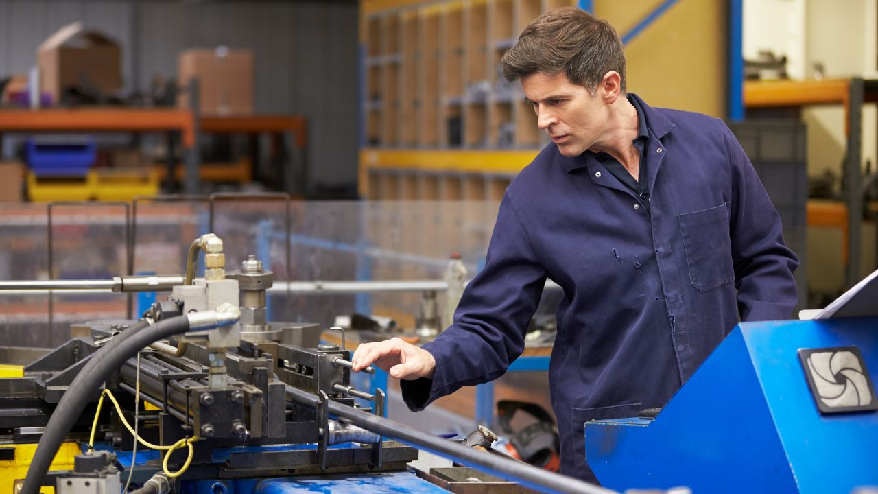
Most tube-bending defects originate from communication failures, not machine limitations. Undefined tolerances, missing material specs, and vague drawings create costly rework cycles that double lead times and inflate budgets. This guide covers the tube bending communication practices that prevent these errors, from early supplier involvement and specification clarity through production-phase checkpoints and first-article verification. Whether you source CNC tube bending or laser tube bending services, stronger client-supplier collaboration starts here.
Key Takeaways
- Communication failures cause most tube-bending defects. Missing tolerances, undefined material grades, and incomplete GD&T callouts lead to rework that re-incurs tooling costs of $2,000 to $10,000+ per setup.
- Early Supplier Involvement prevents late-stage corrections. Engaging engineering before commitments are made optimizes part geometry, reduces lead times, and eliminates costly change orders during production.
- Every technical spec must be explicitly defined. Springback values, temper designations, wall thinning estimates, and industry certifications must accompany every RFQ to protect CNC tube bending accuracy.
- Structured production checkpoints catch deviations early. Formal ECN processes, revision control, first-article inspection, and CMM verification keep quality control dialogue active throughout manufacturing.
- Long-term partnerships compound quality improvements. Shared tooling libraries, established inspection protocols, and centralized traceability documentation reduce error rates and costs across successive projects.
Why Is Tube Bending Communication Essential for Reducing Manufacturing Errors?
Most CNC tube bending defects trace back to communication failures, not machine limitations. When tolerances go undefined, material grades are omitted, or GD&T callouts are missing from drawings, parts fail inspection thresholds and trigger rework cycles that re-incur tooling costs of $2,000 to $10,000+ per setup. Stronger tube bending communication between clients and suppliers prevents these specification gaps — reducing scrap, eliminating missed deadlines, and protecting budgets from the start of every project.
How Do Communication Gaps in CNC Tube Bending Lead to Costly Rework?
Communication gaps produce defects with strict industry limits: flattening/ovality (≤5–8%), inner wall wrinkling (zero tolerance), outer wall thinning (≤10–12%), angular springback (<1° deviation), and radial growth (<2%). When specs are unclear, parts fail these thresholds and require rework — re-incurring custom tooling costs of $2,000 to $10,000+ per setup.
The most common breakdowns in specification clarity include missing bend tolerances, undefined wall thickness or material grade, and vague end-treatment requirements. Relying on XYZ coordinates alone without GD&T callouts fails to define tolerances for point locations or bending radii. With standard lead times already at 2–8 weeks for custom parts, communication-driven rework can double project timelines.
Why Does Weak Specification Clarity Undermine Quality Control Dialogue?
Effective quality control dialogue requires referencing defined standards. PFI Standard ES-24 specifies angular tolerance of ±0.5°. ASME B16.49 allows ±1°. Dimensional tolerance for parallel bends benchmarks at ±0.030″, adding ±0.015″ per additional flange. Ovality must not exceed 8% of average OD per PFI ES-24. Wall thinning limits are ≤15% of nominal for standard work and ≤10% for high-precision applications.
Without these numbers defined upfront, suppliers cannot quote accurately or hold the right tolerances. Holding ±0.005″ costs significantly more than ±0.030″ — vague specs risk over- or under-engineering. Communicating material elongation requirements early using the formula Elongation Required = [(OD/2)/CLR] × 100 prevents material failure during bending and eliminates costly mid-production corrections.
How Can Clear Communication with Tube-Bending Partners Reduce Manufacturing Errors?
Reducing manufacturing errors starts before production begins. Early alignment between clients and suppliers on design intent, material choices, and tolerances eliminates the ambiguity that causes defects downstream. Studies of tube bending failures consistently show that undefined bend radii, omitted springback values, and incomplete secondary operation callouts account for the majority of costly rework. Establishing clear communication protocols — from comprehensive RFQs through DFM reviews — closes these gaps before tooling is cut and production begins.
What Early Alignment Steps Strengthen Client-Supplier Collaboration?
Early Supplier Involvement (ESI) is the highest-impact step in client-supplier collaboration. ESI reduces costs through optimized part geometry, smarter material selection, and fewer secondary operations. It shortens lead times through faster tooling development, better material planning, and fewer late-stage change orders. Leonhardt Manufacturing’s Supplier Scorecard quantifies this: it evaluates partners across six dimensions — manufacturability in quoting, early engineering involvement, capacity planning, cross-functional communication, supply chain risk visibility, and program launch readiness. Scores of 40–50 indicate low disruption risk; below 25 signals high probability of failure. Suppliers where engineering participates before commitments score 5/5, while those where engineering is disconnected from quoting score 1/5.
A comprehensive RFQ reinforces this alignment. It should include material type, grade, and temper; tube OD and wall thickness; bend radii and angles per bend; tolerances; secondary operations; 2D drawings with GD&T; and 3D CAD models in STEP or IGES format.
How Do Structured Error Reduction Strategies Prevent Late-Stage Corrections?
Design for Manufacturability (DFM) reviews are the foundation of structured error reduction strategies. Target a minimum bend radius of 2× tube OD to promote tooling longevity and consistent results. The D-of-bend ratio (CLR/OD) measures severity — as it drops to 1 or below, difficulty escalates, demanding more capable machines, complex tooling, and skilled operators. For ratios below 3, specify higher wall thickness or more ductile material.
Geometry decisions also matter. Designs that complicate fixturing increase setup time and variation. Features positioned too close to the bend area deform during forming. Inadequate corner relief causes distortion or cracking. Addressing these issues during DFM review — not during production — prevents late-stage corrections entirely.
What Technical Specifications Must Be Defined to Protect CNC Tube Bending Accuracy?
Specification clarity is the contract between design intent and finished part. Every undefined variable — material temper, tolerance range, certification requirement — becomes a potential defect in CNC tube bending. Vague specs force suppliers to guess, and guesses introduce variation: holding ±0.005” costs significantly more than ±0.030”, while omitting springback values for materials like 304 stainless steel (2°–3° springback) risks angular deviation beyond acceptable limits. Defining every technical parameter upfront protects accuracy and controls costs.
How Should Tolerances, Bend Radii, and Material Grades Be Communicated?
Standard draw bend radius is 3× tube OD to prevent rupturing. Tighter radii down to 1D are achievable but cost more and carry higher risk. Material-specific springback values must accompany every spec: 304 stainless steel springs back 2°–3°, mild aluminum 1.5°–2°, cold-rolled steel 0.75°–1°, hot-rolled steel 0.5°–1°, and copper/brass 0°–0.5°. Wall thinning is estimated with the formula: Wall Thinning % = (Outside Radius − CLR) / Outside Radius.
Temper designation matters. 6061-T6 aluminum is brittle and cracks during bending; 6061-T4 is formable. Vendor capabilities span diameters from 0.0625″ to 36″ OD and wall thicknesses from 0.035″ to 0.188″+, so specs must be explicit. Industry certifications must also be called out: aerospace requires AS9100D plus NADCAP with ±0.5° tolerance and SPC Cpk >1.67; medical demands ISO 13485 at ±0.1mm; automotive requires IATF 16949; HVAC and construction reference ISO 9001.
Choose standard draw bend radius (3× OD) when cost efficiency and tooling longevity are priorities. Choose tight-radius bending (down to 1D) when compact packaging or space constraints demand it — but budget for higher tooling costs and increased scrap risk. Choose 6061-T4 aluminum when formability matters; choose 6061-T6 only for post-bend heat-treated applications where brittleness during forming is acceptable. Choose AS9100D-certified suppliers when aerospace traceability and ±0.5° angular tolerance are non-negotiable; choose ISO 9001-certified suppliers for HVAC and general construction where standard tolerances apply.
How Do Laser Tube Bending and Secondary Operations Require Advanced Specification Clarity?
Secondary operations need upfront definition: end forming (flare, bead, expand, reduce), welding, cutting to length, hole punching with location and size, threading, coatings, and cleaning/passivation. Weld seam placement defaults to the CLR of the bend. For aesthetic applications, position it on the back. For non-round profiles, never place it in a corner.
Surface finish specs require discipline. Metrics like Ra and Rq are measured per ASME B46.1, but finishes should only be specified where functional or visible. Polishing before forming typically requires post-bend rework. The bend die CLR itself often needs a mirrored finish to prevent tooling wear — but applying broad finish requirements to non-critical areas adds labor and increases scrap risk.
How Should Production-Phase Communication Be Structured to Avoid Delays?
Once production starts, quality control dialogue shifts from planning to execution. Structured checkpoints and verification protocols keep client-supplier collaboration tight and catch deviations before they compound. Without formal milestone reviews, ECN processes, and first-article inspection gates, specification drift goes undetected — and manufacturing from obsolete designs is one of the costliest communication failures in tube bending. Top-tier suppliers maintain on-time delivery rates of 95–100% specifically because they enforce these production-phase communication structures.
What Milestone Checkpoints Improve Quality Control Dialogue During Manufacturing?
A formal Engineering Change Notice (ECN) process governs mid-production modifications in seven steps: identify the problem, create an ECR, review/approve the ECR, create an ECO, review/approve the ECO, communicate the ECN, and implement the change. Multi-level approval workflows with digital signatures and audit trails prevent unauthorized changes. Strict revision control ensures all parties work from the same current document — manufacturing from obsolete designs is one of the costliest communication failures.
Traceability documentation must span the full lifecycle: raw material MTRs (heat number, chemical analysis, mechanical properties), process records, and final inspection reports (FAIRs, CMM data). OEE (Availability × Performance × Quality) monitors production-phase efficiency. On-time delivery benchmarks confirm execution: top-tier suppliers maintain 95–100% rates, with industry leaders like Chicago Metal holding 98% over five consecutive years.
How Can First-Article Verification Support Reducing Manufacturing Errors?
First Article Inspection (FAI) verifies the initial production run meets all design and specification requirements before committing to full volume. For aerospace, FAIRs must conform to AS9102, documenting part number and revision, dimensional measurements against design specs, material certifications, and non-conformance reporting.
Rapid prototyping services accelerate this phase with 2–4 day turnarounds using CNC tube bending, delivering CAD-to-part accuracy. CMM verification confirms dimensional compliance before production scales. The iteration cycle is straightforward: FAI results reveal deviations, teams adjust design or tooling, and re-prototyping continues until specs are met. Industry-standard bend angle tolerance is ±1°, with ovality tolerances ranging from 1.5% to 8% depending on application.
What Are the Benefits of Local Tube Bending for Communication and Error Prevention?
The benefits of local tube bending extend beyond logistics. Geographic proximity transforms client-supplier collaboration from transactional exchanges into real-time partnerships where problems get solved before they become defects. Local suppliers deliver rush orders in 3–5 days versus 6–8 weeks from distant vendors, and cross-functional communication scores highest (5/5) on supplier scorecards when sales, engineering, and production operate as one team. Facility access, direct engineering dialogue, and on-site capability verification all compound to reduce errors and accelerate iteration cycles.
How Does Geographic Proximity Improve Real-Time Problem Resolution?
Local suppliers deliver rush orders in 3–5 days for simple components. Distant suppliers typically require 6–8 weeks for standard custom bends. That speed gap matters most during prototype validation, where pressure and installation testing drive rapid iteration cycles. Proximity compresses each cycle.
Cross-functional communication scores highest (5/5) on supplier scorecards when sales, engineering, and production operate as one team — geographic closeness facilitates this integration. Capacity planning is also more reliable when verified on-site using real equipment, labor, and tooling availability (Score 5) rather than assumed without data (Score 1).
Choose a local tube bending supplier when your project requires rapid prototyping with 2–4 day turnarounds, iterative design validation with pressure and installation testing, or hands-on facility verification of tooling capabilities. Choose a distant supplier only when specialized equipment unavailable locally is required and lead times of 6–8 weeks are acceptable within your project timeline.
Why Do Facility Access and Direct Engineering Communication Strengthen Collaboration?
Walking a supplier’s floor reveals what spec sheets cannot. Standard rotary draw setups include bend die, pressure die, and clamp die. Thin-walled or tight-radius work adds mandrel and wiper die. Facility access lets you visually confirm these capabilities exist and are maintained. Mandrel type must match application: ball mandrels handle multi-radius bends with standard walls, plug mandrels suit large-radius heavy-wall work, and form mandrels serve thicker walls at average radii.
Tooling materials like aluminum bronze alloys extend lifespan through low friction and non-marring performance — qualities observable only in person. Direct engineering dialogue also confirms which bending technology fits each project: rotary draw, mandrel, compression, roll, or heat induction each serve different geometries. CNC multi-stack and all-electric benders handling tubes up to 225mm OD with multi-stack capabilities represent the highest tier of machine sophistication — and in-person assessment is the most reliable way to verify it.
When it makes sense: Local tube bending partnerships deliver the most value during prototype-to-production transitions, tight-tolerance aerospace or medical projects requiring ±0.5° angular accuracy, and high-mix/low-volume runs where setup changes are frequent and direct engineering access prevents costly miscommunication.
How we compare: Local suppliers compress iteration cycles from weeks to days, enable real-time DFM collaboration, and provide on-site tooling verification — advantages that remote suppliers cannot replicate regardless of price. Supplier scorecard data confirms that cross-functional communication, capacity planning reliability, and program launch readiness all score highest with co-located teams.
Expected outcomes: Clients partnering with local tube bending suppliers report shorter lead times (3–5 days for rush orders versus 6–8 weeks), higher first-pass yield through direct engineering feedback loops, and reduced rework costs as shared tooling libraries and established inspection protocols eliminate redundant setup across successive projects.
How Can Long-Term Communication Systems Improve Future Tube Bending Projects?
One-off projects generate data. Long-term communication systems turn that data into compounding improvements. Each completed project should make the next one faster, cheaper, and more accurate. Shared tooling libraries eliminate redundant setup costs, standardized specification templates prevent recurring errors, and established inspection protocols remove the need for custom checking fixtures. Supplier scorecard metrics consistently show that sustained partnerships — where risks are discussed proactively and milestones are planned collaboratively — deliver the highest manufacturing reliability over time.
Why Should Post-Project Reviews Refine Error Reduction Strategies?
Post-project reviews should map every defect to its root cause: flattening traces to insufficient mandrel support, wrinkling to inner wall compression, thinning to outer radius tension, springback to material elasticity, and cracking to insufficient ductility. Tracking these patterns across projects through Statistical Process Control — monitoring bend angle consistency, ovality, wall thinning, and springback — identifies trends and reduces variation over time.
Standardized specification templates formalize this knowledge, capturing part number/revision, material type/grade, tube OD and wall thickness, bend radii/angles, tolerances, finishing requirements, and inspection criteria. Industry-specific benchmarks sharpen the templates further: aerospace tracks angular accuracy to 0.5° with tight-radius bends down to 0.8× tube diameter per AMS 2680; medical tracks tolerances to ±0.1mm with biocompatibility verification and risk management per ISO 14971.
How Does Ongoing Client-Supplier Collaboration Increase Manufacturing Reliability?
Long-term client-supplier collaboration builds shared tooling libraries that reduce costs and lead times on repeat projects. Production volume flexibility scales with relationship maturity — from prototype single-piece runs to 10,000+ parts. Key cost drivers diminish over time: tooling amortizes across higher volumes, setup and programming time decreases, cycle times optimize, and established inspection protocols eliminate custom checking fixtures.
Supplier scorecard metrics improve with sustained partnerships. Supply chain risk visibility scores highest (5/5) when material, tooling, and vendor risks are discussed proactively — not when problems surface (Score 3). Program launch readiness peaks when milestones are planned and reviewed collaboratively (Score 5) versus managed reactively (Score 1). Centralized revision-controlled drawings, comprehensive MTR-to-FAIR traceability, and established ECN workflows reduce error rates across every successive project.
Partner with CRD MFG, Inc. for Precision Tube Bending
CRD MFG, Inc. combines advanced CNC tube-bending capabilities with the hands-on client-supplier collaboration that eliminates manufacturing errors. From early DFM reviews and rapid prototyping to full-volume production with rigorous first-article inspection, our engineering team works directly with yours at every milestone. Reduce rework, shorten lead times, and hold tighter tolerances with a local partner built for specification clarity. Contact CRD MFG, Inc. today to discuss your next project.
Choose CRD MFG when you need a local partner with advanced CNC tube bending capabilities, direct engineering collaboration at every milestone, and rapid prototyping turnarounds of 2–4 days. Our DFM reviews, first-article inspection rigor, and hands-on client-supplier communication are built for projects where specification clarity and tight tolerances are non-negotiable.
When we’re not the right fit: If your project requires exclusively offshore production for high-volume commodity runs with relaxed tolerances, or if you need specialized processes outside tube bending such as stamping or casting, a different supplier may better match your requirements. However, if your work involves precision tube forming for demanding applications like certified petrochemical pipe bending solutions, we encourage you to start a conversation with our engineering team.
