
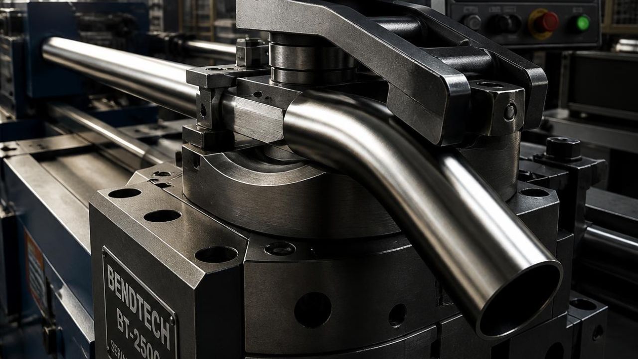
Pipe bending service accuracy determines final dimensional quality of bent tubing across aerospace, automotive, and industrial applications. Angular tolerances have tightened from ±1°–2° industry standards to ±0.05° with modern CNC equipment and servo-electric drives. Position control, ovality limits, and wall thinning now operate within measurable, repeatable parameters supporting high-volume production and critical-tolerance work.
Achieving these tolerances requires understanding material properties, bending method, equipment specifications, and process controls. Tube bending precision depends on centerline radius, springback compensation, mandrel type, and real-time measurement feedback. Modern pipe bender tolerances reflect equipment capability and skilled application of process parameters.
Key Takeaways
- Modern pipe bending service accuracy ranges from ±1° industrial tolerance to ±0.05° aerospace precision with advanced CNC controls
- Springback rates vary by material from 0.3° in copper to 3.5° in titanium, requiring compensation methods
- All-electric servo benders deliver 95% mechanical efficiency and ±0.05° repeatability versus hydraulic systems
- Multi-stack tooling and inline laser inspection reduce setup time by 70% while maintaining tolerance control
- Rotary draw bending provides the tightest precision for complex geometries while induction methods handle large-diameter pipeline work
What Defines Accuracy in Pipe Bending Services?
Accuracy in pipe bending encompasses angular deviation, positional tolerance, ovality control, and wall thinning at the bend. Angular tolerance measures the difference between programmed and actual bend angle in degrees. Positional tolerance defines how closely the finished bend matches its intended coordinate location, typically measured in thousandths of an inch or tenths of millimeters.
Ovality quantifies cross-section deformation during bending as a percentage of original diameter. Wall thinning occurs at the extrados, the outside arc, where material stretches under bending force. Both metrics must remain within code limits and functional requirements.
What Are Typical Angular and Positional Tolerances by Industry?
Standard industrial pipe bending maintains an angular tolerance of ±1°–2° with a positional tolerance around ±0.030″–0.060″ for general fabrication. General CNC operations achieve ±0.5° angular tolerance, tightening to ±0.25° with advanced CNC pipe bending equipment. Linear positioning precision typically reaches ±0.1–0.2 mm with bend-to-bend consistency within ±0.2–0.4 mm.
Automotive applications require ±0.5° angular tolerance and ±0.030″ positional precision for exhaust systems and hydraulic assemblies. Medical device tubing demands ±0.25° angular and ±0.015″ positional tolerance for surgical instruments and diagnostic equipment. Aerospace specifications tighten to ±0.25° angular tolerance with ±0.010″ positional control; critical hydraulic assemblies require tolerances approaching ±0.005″ to prevent leakage at high-pressure connections.
| Industry / Application | Angular Tolerance | Positional Tolerance |
| General fabrication | ±1°–2° | ±0.030″–0.060″ |
| General CNC operations | ±0.5° (to ±0.25° advanced) | ±0.1–0.2 mm |
| Automotive | ±0.5° | ±0.030″ |
| Medical device | ±0.25° | ±0.015″ |
| Aerospace | ±0.25° (±0.005″ critical hydraulic) | ±0.010″ |
How Do Centerline Radius and D-of-Bend Affect Precision?
Centerline radius (CLR) measures the radius to the tube’s neutral axis during a bend and directly influences achievable tolerance. D-of-bend, calculated as bend radius divided by tube outer diameter, serves as a difficulty metric; lower D values indicate tighter bends that challenge tolerance control and require sophisticated tooling. A 2D bend on a 3-inch OD tube uses a 6-inch CLR, while a 1.5D bend compresses to 4.5 inches.
The tightest practical CLR reaches approximately 1× tube diameter, below which mandrel support becomes mandatory to prevent collapse. Design-for-manufacturing guidance recommends a minimum bend radius of 1.5× tube OD to avoid excessive wall thinning and distortion. Standard tooling requires a straight length of 2–3× tube OD between sequential bends for clamp positioning.
What Are Ovality and Wall Thinning Tolerances in Pipe Bending?
Ovality represents the percentage difference between maximum and minimum diameter after bending. Tightest thin-wall precision specifications hold ovality to 1.5% of original OD for applications requiring precise internal flow. Shop standard default sits at 4% for general work, while ASME B31.1 permits up to 8% for ferrous piping with 5D or larger radius and Schedule 40 or heavier wall.
Wall thinning at the extrados follows empirical patterns: approximately 18% at 3D bends, 12.5% at 5D bends, and 8% at 10D bends. ASME B31.3 requires post-bend minimum wall thickness to satisfy pressure-design calculations. Conservative shop allowance for Schedule 80 stainless steel assumes 15% thinning when planning minimum starting wall thickness.
How Does Springback Influence Pipe Bending Accuracy Across Materials?
Springback is elastic rebound occurring when the bending force is removed, measured in degrees of angular deviation. The phenomenon results from the material’s yield strength to elastic modulus ratio; higher ratios produce greater springback. Compensation strategies must account for this material-specific behavior to achieve target angles consistently.
CNC systems store springback values by material and apply overbend corrections automatically. Real-time laser measurement provides closed-loop feedback, adjusting parameters mid-run to counter springback variation between batches. Predictive simulation models achieve springback-prediction accuracy with relative error below 5.79% using Frenet-formula calculations.
What Are Typical Springback Rates for Common Pipe Materials?
Copper C122 exhibits approximately 0.3° springback at a 90° bend with 3D CLR. Aluminum 3003 rebounds around 0.5°, while higher-strength aluminum 5052 shows 0.8° springback. Carbon steel 1020 cold-rolled typically produces 0.75°–1.0° springback; hot-rolled variants range from 0.5°–1.0°.
Stainless 304 demonstrates approximately 2.0° springback, with ranges of 3°–5° depending on hardness and wall factor. Stainless 316 shows slightly higher rebound at 2.2°. Titanium alloys exhibit 2.5°–3.5° springback due to high elastic modulus, while Inconel 625 superalloy reaches 3.0° springback, the highest among common tube materials.
| Material | Typical Springback (90° bend, 3D CLR) |
| Copper C122 | ~0.3° |
| Aluminum 3003 | ~0.5° |
| Aluminum 5052 | ~0.8° |
| Carbon steel 1020, hot-rolled | 0.5°–1.0° |
| Carbon steel 1020, cold-rolled | 0.75°–1.0° |
| Stainless 304 | ~2.0° (range 3°–5°) |
| Stainless 316 | ~2.2° |
| Titanium alloys | 2.5°–3.5° |
| Inconel 625 | ~3.0° |
How Is Springback Compensated in CNC Bending Operations?
Springback compensation in modern CNC operations employs material libraries with angle-by-angle correction factors programmed into the controller. Typical material-conditional correction applies a fixed overbend value, for example, adding 1.8° to the commanded angle for 304 stainless steel. Trial-and-error methods remain common for simple jobs or materials outside standard libraries.
Understanding and compensating for springback increasingly relies on closed-loop inline sensors detecting springback and slippage during production. VCSEL-based sensing systems published in October 2025 enable real-time detection of axial tube slippage at the tool-workpiece interface. Predictive simulation-based overbend calculation integrates with CAD/CAM software to estimate springback before the first bend, reducing scrap and setup iterations.
What Roles Do Mandrel Types and CNC Controls Play in Consistency?
Mandrel types provide internal support to prevent tube collapse during tight-radius bending. CNC control systems automate angle, radius, and mandrel positioning to eliminate operator-dependent variability. These elements form the foundation of repeatable high-precision bending across production volumes.
Modern all-electric axis positioning achieves precision below 0.05 mm per axis move compared to compliance-driven variation in hydraulic circuits. Closed-loop feedback maintains repeatability within ±0.1 mm across production runs, while servo-driven bending heads deliver angular consistency within ±0.1° throughout extended campaigns. CNC setup time compresses to 1–2 minutes versus 10–30 minutes for manual configurations.
Which Mandrel Types Suit Different Pipe Conditions?
Plug mandrels support thicker-wall tubing in larger-radius bends and suit tubes up to 3/8″ diameter. Ball or disc mandrels enable tighter bends in thinner materials, with articulated segments following complex multi-radius geometries. Form mandrels provide robust support for thicker walls at average radii, combining simplified tooling with adequate collapse prevention.
Below 1× tube diameter CLR, mandrel support becomes mandatory to prevent local buckling and excessive ovality. Types of CNC pipe bending machines integrate mandrel control as a programmable axis, coordinating extraction timing with bend completion to minimize surface marking. Wiper dies often accompany mandrels to smooth the inside radius and prevent wrinkling.
How Does CNC Control Enhance Repeatability Versus Manual Methods?
Modern all-electric CNC machines achieve axis positioning precision below 0.05 mm per move, eliminating backlash and hydraulic compliance limiting manual equipment. Closed-loop feedback systems maintain ±0.1 mm repeatability by comparing actual position to programmed targets and correcting deviations in real time. Servo-driven multi-function benders deliver angular consistency within ±0.1°, reducing statistical variation driving scrap rates.
All-electric bend angle repeatability typically reaches ±0.05°, approximately 10× tighter than the ±1° baseline achievable with well-maintained hydraulic manual benders. Modern CNC pipe bending machines store tool libraries, springback corrections, and multi-step sequences in controller memory, ensuring identical execution across shifts and operators. Setup time reduction from 10–30 minutes manual to 1–2 minutes CNC accelerates changeovers and enables economical small-batch production.
How Do Pipe Bending Methods Compare in Precision and Application?
Rotary draw bending clamps the tube and rotates it around a fixed bend die with pressure die contact at the tangent point. Roll bending passes the tube through three rollers that incrementally form gradual curves over multiple passes. Compression bending clamps the tube against a fixed former while a pressure die sweeps it around the radius.
Rotary draw delivers the highest precision, capable of sub-1× tube OD radii with mandrel support, ideal for aerospace hydraulic lines and automotive exhaust systems. Roll bending provides moderate precision suited to large radii beyond rotary-draw capacity, well suited for architectural framing and structural work. Compression bending offers lower precision with higher ovalization risk but serves cost-sensitive general fabrication efficiently.
| Method | Precision Level | Typical Application |
| Rotary draw | Highest; below ±0.5° angular, radii to 1x OD with mandrel | Aerospace hydraulic lines, automotive exhaust, tight multi-plane bends |
| Roll bending | Moderate; large radii beyond rotary-draw capacity | Architectural framing, structural work |
| Compression bending | Lower; higher ovalization risk | Cost-sensitive general fabrication, electrical conduit |
| Induction bending | High for large diameter; 1.5D radius and above | Large-diameter pipeline and power plant piping, 2″–64″ OD |
What Are the Key Differences Between Rotary Draw, Roll, and Compression Bending?
Rotary draw achieves the tightest dimensional control and can bend below 1× tube OD with proper mandrel support. It requires higher tooling investment but excels in tight multi-plane bends for aerospace fuel lines, automotive roll cages, and medical tubing. The method dominates precision applications requiring angular tolerance below ±0.5°.
Roll bending handles large radii exceeding rotary-draw machine capacity, forming gradual curves for architectural railings and structural frames. The method cannot achieve sharp angles or tight radii without buckling. Compression bending suits high-volume, low-tolerance production such as electrical conduit and general fabrication where cost sensitivity outweighs dimensional precision.
When Is Induction Bending Preferred for Large-Diameter Pipes?
Induction bending uses localized electromagnetic heating to 1600–2200°F, softening a narrow band before hydraulic rams bend around a fixed radius arm. The method accommodates diameters from 2″ to 64″ with wall thickness up to 5 inches, spanning ranges impractical for cold-forming equipment. Diameter capacity extends to 1016 mm (40 inches) in some industrial systems.
Induction bending delivers high precision for large-diameter work at 1.5D radius and above, meeting ASME B31.4 and B31.8 pipeline code requirements. Energy sector tube bending for oil and gas pipelines and power plant piping relies on induction methods where diameter exceeds rotary-draw capacity. The process requires post-bend heat treatment to restore heat-affected-zone properties.
What Specifications Differentiate CNC Pipe Bending Machines?
CNC tube bender OD capacity ranges from 12 mm to 250 mm across the commercial market, with specialized equipment extending to 275 mm. Axis count varies from 5-axis mid-tier configurations to 11-axis systems managing multiple simultaneous tooling adjustments. Tonnage, drive type, and measurement precision separate entry-level from aerospace-grade machines.
BLM GROUP electric-series machines handle up to 150 mm OD, while AMOB eMOB models span 5–225 mm and Unison electric platforms accommodate 4–275 mm diameter. Hydraulic pressure die force typically ranges from 500 to 2,000 psi depending on material hardness and tube size. Equipment cost spans approximately $1,000 for manual benders to $154,000 or more for advanced CNC configurations.
How Do Tonnage, Axis Count, and OD Capacity Impact Performance?
BLM Dynamo machines maintain axis positioning tolerance of ±0.1 mm on linear X/T axes and ±0.1° on rotational Y/Z/Q axes. AMOB eMOB 225 deploys 11 servo-driven axes to handle 8-inch (219 mm) tubes with automated radius switching and springback correction. Hydraulic pressure die force scales from 500 psi for small-diameter copper to 2,000 psi for large-diameter stainless steel and titanium.
Higher axis counts enable automated tooling changes and complex multi-plane bend sequences without manual intervention, reducing labor cost and setup time. Choosing a CNC pipe bender requires matching OD capacity, axis configuration, and tonnage to production mix and tolerance requirements. Larger tonnage machines maintain consistent pressure die contact on heavy-wall material, preventing slippage degrading angular accuracy.
What Are the Advantages of Servo-Electric Compared to Hydraulic Drives?
Hydraulic mechanical transmission efficiency typically falls below 80%, while servo-electric systems exceed 95% efficiency by eliminating fluid-circuit losses. Servo-electric processing efficiency reaches approximately double the hydraulic baseline. Energy savings range from 20–40% in typical installations, with some manufacturers citing consumption as low as one-tenth that of equivalent hydraulic machines.
All-electric systems operate at noise levels around 55–60 dB versus higher hydraulic pump noise. Hydraulic bending angle error generally remains under ±1°, while all-electric bend angle repeatability tightens to ±0.05° through precise servo feedback. Servo-electric benders draw power only during active bending cycles rather than maintaining continuous hydraulic pressurization, reducing idle energy consumption.
How Are Industries Mapping Equipment Choices to Pipe Bending Needs?
Aerospace applications require titanium Grade 5/9, Inconel 625/718, and stainless 321/347 tubing for hydraulic and fuel lines. Automotive production uses mild steel, carbon steel, aluminum, and stainless for exhaust systems, roll cages, and hydraulic assemblies. HVAC manufacturing relies on copper, aluminum, and coated steel in small-to-medium diameters for refrigerant lines.
Oil and gas installations demand carbon steel and high-strength alloy pipe in large diameters for pipeline route curves. Industries that rely on custom pipe bending select equipment based on material properties, production volume, and governing quality standards. Medical and semiconductor sectors require cleanroom-capable CNC mandrel bending with angular tolerance to ±0.25° and positional precision to ±0.015 inches.
Which Bending Methods Are Common in Aerospace, Automotive, HVAC, and Oil & Gas?
Aerospace materials including titanium Gr. 5/9, Inconel 625/718, and stainless 321/347 require tight multi-plane bends for hydraulic and fuel lines operating at 3,000–5,000 psi. Rotary draw with mandrel support and wiper dies delivers the ±0.25° angular and ±0.010″ positional tolerances specified by AS9100 standards. Temperature ranges from −65°F to +275°F, and NDT inspection at 95% statistical confidence drives equipment selection toward all-electric servo machines.
Automotive exhaust systems, roll cages, and hydraulic lines use rotary draw for high-volume repeatability at ±0.5° angular tolerance in mild steel, carbon steel, aluminum, and stainless. HVAC production favors all-electric small-radius benders handling copper, aluminum, and coated steel up to 0.86″ diameter in coil-fed automated cells. Oil and gas applications employ induction bending for pipeline-route curves in large-diameter carbon steel, meeting ASME B31.4 and B31.8 ovality limits of ≤2.5% OD reduction.
What Factors Drive Buyer Decisions for CNC Pipe Benders?
Material type and wall thickness determine required bending force, mandrel necessity, and springback compensation complexity. Diameter, CLR, and bend-angle range across the part mix define minimum machine capacity and tooling flexibility needs. Production volume and mix structure, standardized high-volume versus high-mix frequent-changeover, establish ROI timeline expectations ranging from 12 months for standardized runs to 18–24 months for high-mix operations.
Precision and tolerance requirements receive approximately a 95% importance rating from manufacturing decision-makers, driving specification of positioning accuracy and repeatability thresholds. Application sector and governing quality standards, including AS9100 aerospace, IATF 16949 automotive, ASME B31.x piping codes, and FDA/ISO 13485 medical, impose documentation and process-control requirements favoring CNC over manual equipment. Future capacity needs influence multi-stack tooling adoption and all-electric platform selection where product diversification is anticipated.
What Technological Advances Are Improving Modern Pipe Bending Accuracy?
Servo-electric bending platforms have expanded from small-diameter HVAC applications to large-capacity industrial machines handling 150–225 mm tubes. Multi-stack tooling enables automated radius and diameter switching within production cycles, reducing setup time by 70% versus manual tool changes. Inline laser inspection provides real-time feedback loops measuring bend angle against programmed references during production, enabling closed-loop correction before parts leave the machine.
Digital twin simulation integrates physics-based process modeling with collision detection for offline programming and cycle-time estimation. Industry 4.0 connectivity embeds IoT sensors for predictive maintenance, remote diagnostics, and production metrics. CNC machines now represent an estimated 85% of new tube-bending equipment installations, with all-electric systems comprising 32% of new placements driven by energy efficiency and precision requirements.
How Is Servo-Electric Bending Evolving Recently?
BLM GROUP launched the Smart-One all-electric small-radius tube bender in February 2025, targeting HVAC and automotive production up to 0.86″ diameter. The ELECT150 fully electric machine handles up to 150 mm diameter, demonstrated at TUBE & WIRE 2024 bending 110 mm tubes to 90 mm average radius. BLM’s TechForward 2026 event in June previewed AI-driven automatic bending-parameter calculation and single-machine coil-to-tube processing.
Unison Ltd presented its largest all-electric machine, the Breeze 80 mm, at MACH 2026 alongside the servo-assisted EvBend 2000 for tubes up to 50 mm diameter. AMOB released the eMOB 225 in November 2025, one of the largest fully electric benders available, handling 8-inch (219 mm) tubes with 11 servo-driven axes. The machine integrates multi-stack tooling and automatic springback compensation software on an OMRON PLC platform.
What Benefits Do Multi-Stack Tooling and Inline Laser Inspection Offer?
Multi-stack tooling mounts multiple tool sets on one bending head, enabling automated radius and diameter switching within the production cycle. Schwarze-Robitec reports 70% setup-time reduction from multi-stack configurations on heavy-duty CNC lines, particularly valuable where large dies would otherwise require crane-assisted manual changeover. The configuration eliminates repeated manual tool swaps, reducing labor cost and scrap from setup errors.
Inline laser measurement establishes real-time feedback loops measuring bend angle against programmed reference during production rather than post-process inspection. Hexagon TubeInspect provides turnkey non-contact optical measurement cells for integration with bending machines, enabling closed-loop parameter adjustment. Vision Components VC nano 3D-Z laser profiler employs blue high-power laser triangulation to cope with reflective metal surfaces, measuring bend angle in real time.
How Do Simulation Software and Industry 4.0 Integration Enhance Precision?
Digital twin technology creates physics-based simulation of the complete bending process for offline programming, collision detection, and cycle-time estimation. Transfluid t project 5.0 incorporates digital twin capabilities with cloud storage and product databases covering complete tube assemblies. BendPro and BendPro SIM provide CAD/CAM interfaces with automatic bend-sequence optimization and support for wide manufacturer libraries including Addison, Chiyoda, Eaton Leonard, and Pines equipment.
Unison 3D simulator employs AI-driven bend-sequence optimization with fully automated collision detection across the complete Breeze machine range. Springback-prediction algorithms achieve average relative error below 5.79% using Frenet-formula models for variable-curvature tubes, reducing first-part scrap. Industry 4.0 integration embeds IoT sensors for predictive maintenance, flagging issues before breakdown, while production-metrics analytics feed manufacturing execution systems and ERP platforms for real-time shop-floor visibility — the same digital infrastructure that coordinates advanced laser tube cutting solutions and robotic welding cells on a shared production timeline.
Achieving Optimal Pipe Bending Service Accuracy with Modern Equipment
Modern pipe bending service accuracy reflects the convergence of servo-electric drive precision, real-time measurement feedback, and sophisticated material compensation algorithms. Angular tolerances tightened from ±1°–2° industry baseline to ±0.05° repeatability enable critical aerospace and medical applications previously requiring secondary operations. All-electric machines deliver 95% mechanical efficiency while consuming approximately 20–40% less energy than hydraulic equivalents, addressing both precision and sustainability requirements.
Multi-stack tooling and digital twin simulation compress setup time by 70% while maintaining dimensional consistency, supporting profitable high-mix production alongside traditional high-volume runs. Inline laser inspection closes the feedback loop during bending cycles rather than post-process inspection, reducing scrap and accelerating throughput. CRD MFG combines advanced bending technology with dedicated project management to deliver consistent quality from prototype through full production, eliminating multi-vendor complexity that drives cost and lead time.
Talk to CRD MFG, Inc. About Your Pipe Bending Tolerances
CRD MFG, Inc. runs all-electric CNC pipe bending, laser tube cutting, and robotic welding in one Placentia, California facility, with Faro Arm and VTube inspection confirming angular, positional, ovality, and wall-thinning results before parts ship. A dedicated project manager reviews your prints, confirms achievable tolerances for your material and geometry, and coordinates tooling and production from first article through full volume, whether the work falls under AS9100, IATF 16949, or FDA/ISO 13485. The same process discipline applies to heavy-wall petrochemical pipe bending solutions, where ovality and wall-thinning tolerances directly affect system safety.
Call CRD MFG, Inc. at (714) 871-3300 or request a quote to review your pipe bending tolerance requirements.
Frequently Asked Questions
Q1. What angular tolerance can CRD MFG, Inc. hold on CNC pipe bending?
CRD MFG, Inc. bends tubing on all-electric CNC equipment capable of ±0.05° angular repeatability, with the production tolerance set by the application, typically ±0.5° on general industrial parts and ±0.25° or tighter on aerospace and medical assemblies. Actual tolerance depends on material, wall thickness, centerline radius, and part geometry. A CRD MFG project manager reviews the print and confirms the tolerance band before quoting.
Q2. How much does tighter pipe bending tolerance add to project cost?
Tighter tolerances generally add cost through slower cycle times, additional mandrel and tooling requirements, and inline inspection, though the exact increase depends on material, diameter, and production volume. High-mix runs with frequent tolerance changes carry a longer ROI timeline than standardized high-volume production. Sharing part volume and tolerance requirements upfront lets CRD MFG quote tooling and cycle time accurately rather than applying a flat premium.
Q3. Which pipe bending method delivers the tightest tolerances?
Rotary draw bending with mandrel support delivers the tightest dimensional control among common methods, capable of angular tolerance below ±0.5° and radii below 1x tube outer diameter. Roll bending and compression bending trade precision for larger radii or lower tooling cost. Induction bending fills large-diameter pipeline work where rotary draw capacity is exceeded.
Q4. How is springback accounted for during CNC pipe bending?
CNC controllers store material-specific springback values and apply overbend corrections automatically, drawing on libraries built from materials such as copper, aluminum, carbon steel, stainless steel, and titanium. Inline laser measurement adds closed-loop feedback that adjusts bend parameters mid-run when springback varies between batches or lots. Predictive simulation software estimates springback before the first bend, which reduces first-part scrap on new programs.
Q5. What industries require the tightest pipe bending tolerances?
Aerospace hydraulic and fuel lines, medical device tubing, and semiconductor equipment typically require the tightest angular and positional tolerances, often ±0.25° or tighter with positional control to ±0.015 inches or better. Automotive exhaust and hydraulic assemblies generally run at ±0.5° angular tolerance, while general industrial fabrication allows ±1°–2°. Standards such as AS9100, IATF 16949, and FDA/ISO 13485 set the documentation and process-control requirements behind these tolerance bands.
