
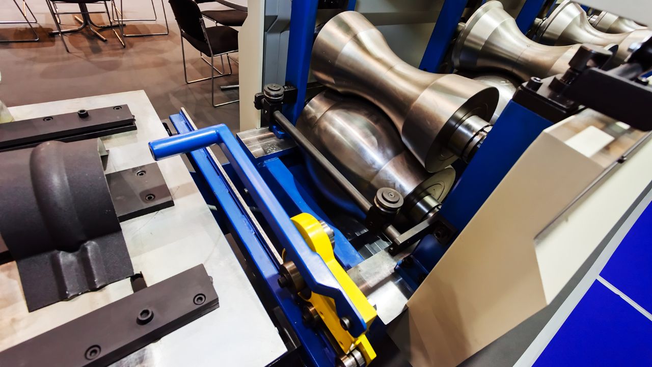
Custom pipe bending prototyping is how complex tube designs move from concept to production-ready parts without costly guesswork. The process combines CAD-driven design, CNC tube bending, and laser tube cutting to validate geometry, tolerances, and material performance before full-scale manufacturing begins. Getting it right at the prototype stage prevents rejected parts, blown budgets, and missed deadlines downstream. This guide covers every phase — from initial design and DFM review through prototype testing, production scaling, and timeline optimization — backed by the data that drives real manufacturing decisions.
Key Takeaways
- DFM reviews are the highest-leverage step. Catching collisions, springback risks, and flange issues before tooling is committed prevents exponentially higher costs downstream.
- The prototype-to-production timeline runs 10–14 weeks across seven stages — from DFM review through production ramp-up — with first article production typically spanning 1–3 weeks.
- Material choice drives everything. Stainless steel demands 50% more bending force than carbon steel, and springback ranges from 0.3° (copper) to 3.0° (Inconel) — making prototype testing essential for validating forming behavior.
- Per-part costs drop over 99% from prototype ($500–$5,000) to high-volume production ($3–$30) as NRE costs amortize across volume, with the hard tooling break-even sitting near 1,875 units.
- Soft tooling compresses timelines dramatically — 3–5 weeks at $3,000–$12,000 versus 8–16 weeks at $15,000–$80,000 for hard tooling — making it the clear choice for runs under 5,000 units.
What is Custom Pipe Bending Prototyping and Why is it Essential?
Pipe bending prototyping bridges the gap from concept to production by validating designs before full-scale manufacturing begins. It is the fastest path to production-ready parts that meet exact specifications.
Custom Pipe Fabrication Uses CAD-Driven CNC Processes Instead of Fixed Stock Components
Standard tubing ships in fixed geometries — DOM tubing ranges from 3⁄8″ to 10.5″ OD with wall thicknesses of 0.028″ to 0.625″ in 17–24 foot mill lengths. That is where standard methods stop. Custom pipe fabrication starts there. CNC tube bending and laser tube cutting transform raw stock into complex multi-bend assemblies with end-forms like flaring, beading, and swaging, plus integration points for fittings, brackets, and sensors.
Design begins in SolidWorks, AutoCAD, or CATIA, where dedicated tube routing modules define centerline geometry, bend radii, and end-form requirements. Bending feasibility is quantified by the K-factor — derived from the centerline radius (CLR), OD, and wall thickness. A K-factor above 0.30 means straightforward bending. Below 0.10, specialized tooling like mandrels and wiper dies becomes mandatory. Below 0.05, the bend is not feasible under normal conditions. This analysis happens before any metal is touched, covering volumes from single prototypes to 10,000+ unit runs.
Precision Prevents Collapse, Wrinkling, and Part Failure
Every custom tube fabrication timeline depends on getting four parameters right from the start: CLR, OD, wall thickness, and D-of-bend ratio (CLR ÷ OD). The minimum allowable bend radius is typically 1.5× the OD, but material choice shifts everything. Stainless steel 304 reduces the effective K-factor by roughly 20%, 316 by 25%, and aluminum 6060 by 35% — each requiring progressively more force and wider radii.
Formability hinges on elongation. Materials above 20% elongation handle complex bends well. Below 12%, expect annealing or hot bending. Stainless steel demands approximately 50% more bending force than carbon steel, making prototype testing essential for validating that designs survive the forming process intact.
What Steps Are Involved in Turning a Custom Pipe-Bending Prototype into a Production-Ready Part?
Moving from concept to production follows a structured sequence. Each stage gates the next — skip one, and defects compound downstream.
DFM Reviews Catch Costly Errors Before Tooling Is Committed
Design for Manufacturability (DFM) and DFMA reviews use simulation tools to visualize bend behavior, flag springback risks, and identify collisions before any metal is cut. Engaging expert tube benders early in this phase eliminates engineering revisions, reduces material waste, and improves reliability. The problems DFM catches — part-to-machine collisions from long flanges, cracking from inadequate corner clearance, distortion near bend zones, flange misalignment — become exponentially more expensive to fix after tooling is committed.
Cost drivers crystallize here too. Material type, tooling requirements, part complexity (number of bends, tightness of radii, compound geometries), and secondary operations like welding or coating all shape the quote. Standard diameters and wall thicknesses keep costs down. Non-standard radii, unique diameters, and specialty alloys add cost fast — especially on low-volume orders with minimum order quantities.
Seven Stages Span 10–14 Weeks from DFM Review to Production Go-Live
The custom tube fabrication timeline from pipe bending prototyping through production-ready parts follows a defined sequence: Design and DFM review (weeks 1–2) leads to customer approval, then tooling and setup (weeks 2–4), first article production (weeks 3–5), validation and inspection (weeks 4–6), iterative refinement (weeks 5–8), PPAP or FAIR documentation (weeks 8–10), and production ramp-up (weeks 10–14).
Tooling finalization means transitioning from soft or bridge tooling to production-grade hard tooling — machining bend dies, clamp dies, pressure dies, mandrels, and wiper dies, then heat treating for durability. Process documentation must be detailed enough for any trained operator to produce conforming parts, per ISO 9001:2015 requirements. Supply chain scaling from prototype volumes of 1–10 units to production runs of 100–10,000+ demands raw material agreements, qualified secondary suppliers, and inventory systems like JIT or Kanban.
What Role Do CNC Tube Bending and Laser Tube Cutting Play in Prototyping?
CNC tube bending and laser tube cutting are the two core technologies behind modern pipe bending prototyping. Together, they turn CAD geometry into finished parts with minimal manual intervention.
CNC Tube Bending Delivers Unmatched Repeatability Across Complex Multi-Bend Geometries
CNC bending programs accept two data formats: LRA (Length-Rotation-Angle) for sequential bend definitions and XYZ coordinates for complex 3D geometries. Direct import from STEP or IGES files is standard — the controller processes either format in milliseconds regardless of whether the part has 2 bends or 20. Intelligent programming optimizes the bend sequence to minimize machine rotations, avoid part collisions, and keep every bend accessible.
Each bend requires five matched die components: bend die, clamp die, pressure die, mandrel, and wiper die — all sized to the specified CLR. Springback compensation is where precision lives. Methods range from trial-and-error to material-specific libraries, real-time laser feedback systems, and predictive algorithms. The stakes are material-dependent: copper springs back just 0.3° on a 90° bend at 3D CLR, carbon steel about 1.0°, aluminum 6061-T6 hits 1.5°, stainless 304 reaches 2.0°, and Inconel 625 demands 3.0° of compensation. Miss these values and every part in the run is out of spec.
Laser Tube Cutting Eliminates Secondary Processes and Compresses Lead Times
The advantages of laser tube cutting start with consolidation. CNC-controlled infrared lasers produce complex geometries across pipe, tube, angle, box, and channel profiles — eliminating secondary operations like sawing, drilling, and deburring in a single pass. That means fewer setups, lower cost, and shorter custom tube fabrication timelines without sacrificing quality.
Laser cutting also handles shapes that conventional methods cannot achieve, across both metals and plastics. Because CAD data flows directly from cutting to CNC bending operations, the entire concept to production workflow stays digital end to end.
How Does Prototype Testing Ensure Quality in Production-Ready Parts?
Prototype testing is the firewall between a promising design and a failed production run. Every inspection method and quality system exists to catch defects before they scale.
CMMs, Laser Scanners, and Pressure Testing Validate Geometry, Tolerances, and Structural Integrity
Dimensional inspection starts with CMMs, which use touch probes to measure discrete surface points at sub-millimeter accuracy. 3D laser scanners capture full tube geometry in seconds, generating point clouds compared directly against the CAD model. Specialized systems like TUBEINSPECT use multi-camera photogrammetry and measure a part in under 30 seconds.
Tolerance requirements vary sharply by industry. Aerospace (FAIR) demands ±0.25° angular and ±0.010″ positional accuracy with max wall thinning of 10%. Automotive (PPAP) allows ±0.5°–1.0° angular and ±0.030″ positional with 15% wall thinning. Industrial and HVAC applications permit ±2.0° angular and ±0.060″ positional. PFI Standard ES-24 governs baseline pipe bending prototyping tolerances: ±0.5° angular, ±1/8″ linear for dimensions under 12″. Ovality limits sit at 10% of OD, wrinkle height at 3% of nominal pipe size — neither permitted in aerospace or medical. Hydrostatic pressure testing per ASME B31 requires minimum 1.5× design pressure held for 10 minutes, exceeding 10,000 PSI in high-pressure applications.
Formal Quality Systems Prevent Defects from Reaching Production-Ready Parts
Each regulated industry enforces its own gate. PPAP (automotive) requires DFMEA, process flow diagrams, control plans, and statistically significant dimensional results before production approval. FAIR (aerospace, AS9102) verifies every dimension and material spec against the engineering drawing. DHF (medical, FDA 21 CFR Part 820) compiles the complete design history from inputs through validation.
Wall thinning drives many rejection decisions. At 1D CLR, stainless steel thins approximately 32%, carbon steel 28%, aluminum 24%. At 3D CLR, those numbers drop to 15%, 12%, and 10% respectively — right at the common 15% industry limit. Work hardening on the outer wall and wrinkling on the intrados compound the risk, especially with thin-walled tubes and tight radii.
What Are the Production Speed Benefits of CNC Laser Cutting in Custom Pipe Fabrication?
The production speed benefits of CNC laser cutting come down to fewer setups, faster changeovers, and automation that keeps machines running instead of waiting.
CNC Laser Cutting Consolidates Multiple Operations into a Single Automated Pass
Laser cutting replaces sawing, drilling, and deburring with one process. That alone eliminates multiple setups and vendor handoffs. Pair it with automated tube loading and unloading, weld seam detection and orientation, and direct CAD-to-machine integration, and the entire custom pipe fabrication workflow stays continuous.
Changeover speed compounds the gains. Automated clamping and positioning systems reduce tool changeover times by approximately 20%. Simplified manual changeover solutions cut that window from 15 minutes to as little as 3 minutes — critical when running mixed part numbers or short prototype batches alongside production volumes.
Faster Cycles Collapse Per-Part Costs by Amortizing NRE Across Volume
The cost curve in custom pipe fabrication is steep. A single prototype runs $500–$5,000 per part with a 1–3 week lead time. At low volume (50–500 units), that drops to $100–$500 per part over 3–6 weeks. Mid-volume production (500–5,000 units) lands at $10–$100 per part. High volume (5,000+ units) reaches $3–$30 per part — a reduction of over 99% from prototype pricing.
This collapse is driven by amortizing NRE costs — tooling, programming, setup — across larger runs. The hard tooling break-even decision is pivotal. A simplified calculation suggests roughly 851 units. Factor in time value of money, design change probability, and inventory carrying costs, and the true break-even sits closer to 1,875 units. At the per-part level, total cost drops from $4,500 for a single prototype to $2,100 at 50 units, $900 at 500 units, and $450 at 5,000 units. Faster production cycles through CNC laser cutting accelerate the path across every tier.
How Can You Minimize the Custom Tube Fabrication Timeline Without Sacrificing Quality?
Timeline compression without quality loss comes down to tooling strategy, adaptive technology, and material decisions made early.
Soft Tooling, Adaptive Bending, and Closed-Loop Feedback Shorten Every Phase
The tooling decision sets the pace. Soft tooling (aluminum, silicone, carbon fiber composites) costs $3,000–$12,000 with a 3–5 week lead time, handles 500–10,000 shots at ±0.030″ precision, and accommodates design changes cheaply. Hard tooling (hardened steel, nickel alloys) runs $15,000–$80,000 over 8–16 weeks but delivers ±0.010″ precision across 500,000–1M+ shots. For volumes under 5,000 units, soft tooling compresses the custom tube fabrication timeline dramatically.
Choose soft tooling if your run is under 5,000 units and designs may still change. Choose hard tooling when volumes exceed 5,000 units and geometry is finalized.
First article production typically spans 1–3 weeks. From there, advanced CNC systems with adaptive bending automatically refine parameters based on measured results — each successive part improves on the last. Iterative refinement cycles feed CMM or laser scan data directly back into the programming system, closing deviations without manual intervention.
Simulation, Material Strategy, and Reverse Engineering Cut Weeks from the Process
Cycle time optimization from prototype to production yields a typical 30–50% improvement as processes are refined and automation introduced. 3D bending simulation tools test bend sequences virtually before consuming material, eliminating costly physical trial-and-error.
Material selection directly impacts lead time. Carbon steel is readily available at $2–$5/lb. Titanium and exotic alloys at $25–$100+/lb carry longer procurement windows and minimum order quantities.
|
Material |
Tensile (MPa) |
Elongation (%) |
Min CLR (×OD) |
Cost/lb |
|
Carbon Steel 1020 DOM |
552 |
15 |
2.0× |
$2–$5 |
|
Stainless 304 |
515 |
40 |
2.5× |
$8–$12 |
|
Stainless 316 |
515 |
40 |
2.5× |
$10–$15 |
|
Aluminum 6061-T6 |
310 |
12 |
3.0× |
$4–$8 |
|
Aluminum 3003 |
130 |
30 |
1.5× |
$3–$6 |
|
Titanium Gr.2 |
345 |
20 |
3.0× |
$25–$50 |
|
Copper C122 |
220 |
35 |
1.5× |
$3–$5 |
|
Inconel 625 |
827+ |
30 |
3.5× |
$50–$100 |
Choose carbon steel when cost efficiency and availability are priorities. Choose stainless steel when corrosion resistance or regulatory compliance drives the specification. Choose aluminum when weight reduction is critical. Choose titanium or exotic alloys only when extreme strength-to-weight ratios or high-temperature performance are non-negotiable.
Reverse engineering with Faro Arms, blue light scanners, and VTube Inspection Software enables rapid digitization of existing parts — bypassing design-from-scratch timelines entirely.
Partner with CRD MFG, Inc. for Your Next Custom Pipe Bending Project
CRD MFG, Inc. is a full-service manufacturing partner in Placentia, California, specializing in CNC tube bending, laser tube cutting, and precision fabrication from prototype through production. Every project gets a dedicated project manager — one point of contact from concept to delivery. Whether you need a single prototype or a 10,000+ unit production run, our team has the advanced equipment, in-house tooling, and manufacturing expertise to bring complex designs to life on time and on spec. Request a quote today.
