
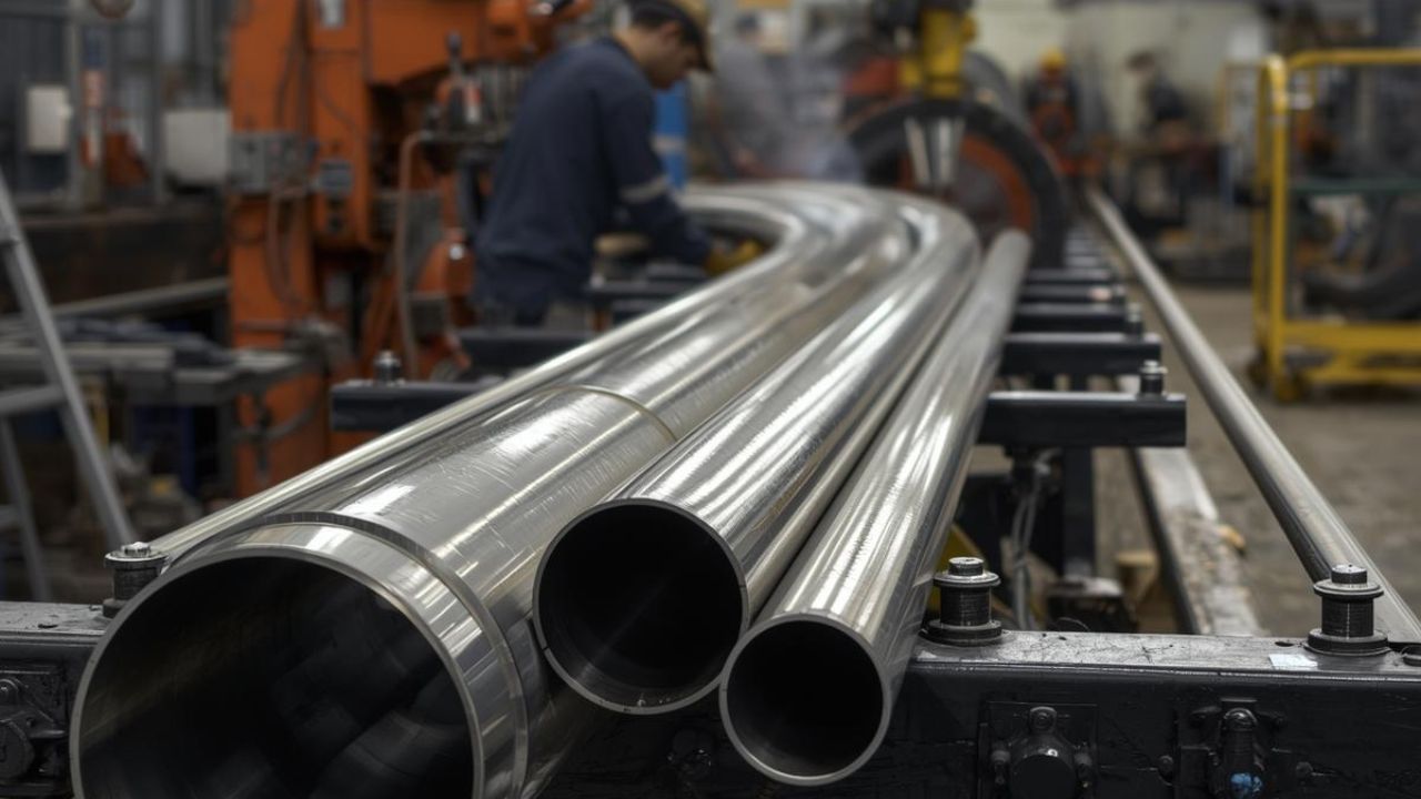
Tube and pipe benders have advanced through CNC automation, servo-electric drives, and integrated laser measurement, transforming manufacturing precision across industries. Modern CNC tubing bender platforms hold angular tolerances within ±0.1° and positional repeatability below ±0.05 mm while cutting energy use by up to 40% versus hydraulic systems. Multi-stack tooling, digital twin simulation, and closed-loop feedback let manufacturers produce complex geometries with first-time-right accuracy across aerospace, automotive, medical, and industrial sectors.
Here’s what we break down: CNC and servo-electric bending precision, springback and wall-thinning limits by material, laser measurement and simulation software, and how Industry 4.0 connectivity and industry needs shape machine selection. See CRD MFG, Inc.’s CNC tube bending services for how these capabilities come together in production.
Key Takeaways
- Rotary draw bending achieves centerline radii below 1x tube diameter with mandrel support, delivering angular tolerances within ±0.25° for aerospace and medical applications
- Servo-electric CNC systems cut energy consumption by 20–40% and improve positioning precision to ±0.05 mm per axis compared to hydraulic machines
- Springback compensation ranges from 0.3° for copper to 3.0° for Inconel 625; CNC material libraries and laser feedback enable closed-loop correction within ±0.1 mm repeatability
- Multi-stack tooling removes manual changeovers, cutting setup time by 70% and enabling automated bend-radius switching within a single production cycle
- Industry 4.0 integration with IoT sensors and MES platforms supports predictive maintenance, real-time analytics, and AI-driven parameter optimization across connected production lines
Tube and Pipe Benders Rely on Distinct Core Types and Functions
Types of CNC pipe bending machines determine achievable precision, cycle time, and geometric complexity. Rotary draw, roll, compression, and induction bending each serve distinct requirements based on centerline radius, wall thickness, and tolerance.
Rotary Draw, Roll, and Compression Bending Differ in Precision and Application
Rotary draw bending clamps the tube and rotates it around a fixed bend die while a pressure die holds the tangent point, delivering the highest precision with centerline radii below 1× tube outer diameter under mandrel support. Roll bending passes the tube through three rollers for large radii beyond rotary-draw capability, while compression bending clamps the tube against a fixed former for lower precision and greater ovalization. Induction bending applies localized heating at 1600–2200°F and a hydraulic ram to bend large-diameter tube at 1.5D radii and above, though it requires post-bend heat treatment. Rotary draw holds roughly 35–45% market share, with roll bending near 30%.
Typical Tolerances and Precision Standards Vary by Application
Tolerance requirements tighten with application risk. The table below summarizes standard angular and positional tolerances by industry, plus the ultra-precision and general CNC ranges achievable with today’s equipment.
| Application | Angular Tolerance | Positional Tolerance |
|---|---|---|
| Standard industrial | ±1°–2° | ±0.030″–0.060″ |
| Automotive | ±0.5° | ±0.030″ |
| Medical device | ±0.25° | ±0.015″ |
| Aerospace | ±0.25° (±0.005″ critical hydraulic) | ±0.010″ |
| Ultra-precision | ±0.1°–0.25° | ±0.05–0.15 mm |
| General CNC (standard / advanced) | ±0.5° / ±0.25° | ±0.1–0.2 mm; ±0.2–0.4 mm bend-to-bend |
Mandrel Type Selection Affects Bend Repeatability
Plug mandrels suit thicker walls and larger radii up to 3/8″ diameter. Ball or disc mandrels support tighter bends, thinner materials, and multi-radius geometries, while form mandrels work well for thicker walls at average radii. Below 1× tube diameter centerline radius, mandrel support becomes mandatory to prevent buckling.
CNC bending accuracy with mandrel support enables closed-loop feedback to hold repeatability within ±0.1 mm across production runs when paired with servo-driven positioning and real-time measurement.
Tube and Pipe Benders Gain Precision Through CNC Technology
CNC tube bending systems automate angle control, mandrel positioning, and carriage movement to eliminate operator variability. Modern platforms integrate servo-electric drives, multi-axis coordination, and programmable springback compensation to achieve aerospace-grade repeatability across high-mix production cycles.
Key CNC Machine Specifications Define Capacity and Precision
General CNC angular tolerance reaches ±0.5° standard or ±0.25° with advanced controls, with linear positioning tolerance of ±0.1–0.2 mm and bend-to-bend tolerance of ±0.2–0.4 mm. CNC tube outer diameter capacity commonly ranges from 12 mm to 250 mm depending on the machine platform. Common configurations use five axes (X, Y bend, Z rotation, T carriage, and a booster axis), and all-electric machines achieve bend angle repeatability within ±0.05°, with mechanical transmission efficiency above 95% versus under 80% for hydraulic systems.
Servo-Electric Drives Deliver Higher Efficiency Than Hydraulic Systems
Servo-electric systems deliver mechanical transmission efficiency above 95%, versus below 80% for hydraulic systems, which lose efficiency to fluid compression and circuit losses. Energy savings with servo-electric platforms typically run 20–40%, since these systems draw power only during active bending. Servo-electric machines also run quieter, around 55–60 dB.
Hydraulic bending angle error generally stays under ±1° on well-tuned systems, while Modern CNC pipe bending machines using all-electric servo control achieve axis positioning precision below 0.05 mm per move and bend angle repeatability within ±0.05°.
Multi-Stack Tooling Enables Automated Changeovers
Multi-stack tube benders mount multiple tooling sets on one bending head, enabling automated switching of bend radii and diameters within a single production cycle and eliminating manual tool swaps. Schwarze-Robitec multi-stack systems cut setup time by 70% in heavy-duty applications.
CNC tube bending setup time drops to 1–2 minutes, versus 10–30 minutes for manual configurations, when multi-stack tooling pairs with programmable positioning; see Understanding how CNC tube bending works for more on this automation.
Material Selection Drives Springback Behavior in Modern Bending
Material selection directly influences springback magnitude, wall thinning severity, and achievable centerline radius. Springback is the elastic rebound in degrees after a bend is released, scaling with the ratio of yield strength to elastic modulus.
Material Selection Determines Springback Compensation Requirements
Springback magnitude scales with the ratio of yield strength to elastic modulus, so softer, more ductile metals rebound less than high-strength alloys. The table below compares springback at a 90° bend across common tube materials.
| Material | Springback at 90° Bend |
|---|---|
| Copper C122 | 0.3° (approx. 3D radius) |
| Aluminum 3003 | 0.5° |
| Aluminum 5052 | 0.8° |
| Carbon steel 1020, hot-rolled | 0.5°–1.0° |
| Carbon steel 1020, cold-rolled | 0.75°–1.0° |
| Aluminum 6061-T6 | 1.5° |
| Stainless 304 | 2.0° (some sources: 3°–5°) |
| Stainless 316 | 2.2° |
| Titanium alloys | 2.5°–3.5° |
| Inconel 625 | approx. 3.0° |
Compensation methods include trial-and-error adjustment, CNC-stored material libraries with angle-specific corrections, real-time laser feedback, or predictive simulation-based overbend calculation; see Understanding and compensating for springback for the full process. Titanium and Inconel require substantially greater overbend than aluminum or copper.
Wall Thinning and Ovality Limits Require Careful Management
Tightest thin-wall precision specifications limit ovality to 1.5%, while shop standard tolerance typically allows 4% and general guidelines permit around 5%. ASME B31.1 sets an 8% maximum difference threshold for ferrous materials at 5D radius or greater with Schedule 40 wall or heavier. Wall thinning reaches 18% at 3D bends, 12.5% at 5D, and 8% at 10D. ASME B31.3 requires post-bend wall thickness to satisfy the pressure-design formula Pt = (Ro − R) / Ro, where Ro is the outside radius, and R is the centerline radius.
CNC Systems Measure and Correct Springback in Real Time
Compensation methods span trial-and-error for simple jobs, CNC-stored material libraries, real-time laser feedback, and predictive simulation. High-end machines from Eaton Leonard, Pines, and Unison Breeze support springback correction tables natively.
Closed-loop CNC feedback enables repeatability within ±0.1 mm across production runs when laser sensors measure actual bend angles and adjust subsequent bends automatically; see Material selection for tube bending for how alloy choice drives the correction needed.
Laser and Optical Measurement Technologies Enhance Bending Precision
Inline laser and optical measurement systems integrate with CNC controls to provide real-time dimensional feedback during production cycles, enabling closed-loop correction of springback, slippage, and positional errors before parts leave the bending station.
Inline Inspection Tools Enable Real-Time Feedback
Hexagon TubeInspect provides a turnkey non-contact optical measurement cell for tube bending machines. The Vision Components VC nano 3D-Z laser profiler uses laser-triangulation angle sensing to measure bend angles in real time despite reflective metal surfaces. Third-party CMM and scanning systems from Romer, Faro, AICON, and Creaform integrate with advanced CNC platforms to verify complex geometries.
Tube assembly services increasingly build these measurement cells in before parts move to welding or final assembly.
Closed-Loop Systems Integrate Laser Sensing With CNC Controls
Closed-loop CNC feedback enables repeatability within ±0.1 mm across production runs by continuously comparing measured geometry to programmed targets, with servo-driven multi-function benders achieving angular consistency within ±0.1° when laser feedback adjusts bending parameters automatically. Unison laser springback correction technology feeds measurement data directly into the CNC controller, which recalculates subsequent bend angles for material-specific rebound, eliminating iterative manual adjustment in high-mix environments.
Inline Springback and Slippage Detection Continue to Advance
A 2025 VCSEL sensor system detects axial tube slippage at the tool-workpiece interface using vertical-cavity surface-emitting laser technology. Unison Opt2Sim Scan is a 3D measuring device built for springback correction that feeds dimensional data directly into the Breeze machine control system, eliminating the manual measure-and-adjust cycles operators previously relied on. Academic research shows inline laser sensing embedded in clamping dies enables real-time parameter adjustment during bending rather than only post-process inspection.
Software Innovations Improve Bend Sequencing and Simulation Accuracy
Physics-based simulation software enables first-time-right bending by modeling material behavior, collision zones, and optimal bend sequences before physical tooling setup, integrating CAD/CAM programming, digital twins, and AI-driven optimization to reduce scrap and speed programming cycles.
Physics-Based Simulators Optimize Bend Programming
The Unison 3D simulator uses a physics-engine-based platform with AI sequence optimization that evaluates possible bend orders and selects the path with minimum cycle time, detecting collision risks, tooling interference, and springback errors before physical setup. BLM GROUP VGPNext CAD/CAM software integrates with the company’s electric bending machines to generate tool paths automatically from imported geometry. BendPro and BendPro SIM add collision simulation and cycle-time estimation, with a manufacturer library covering Addison, Chiyoda, Crippa, Eaton Leonard, Hines, Pines, and SOCO.
Digital Twins and Cloud Integration Offer Production Benefits
Transfluid t project 5.0 introduces a digital twin of the complete bending process with cloud data storage through CloudDrive, enabling offline programming, virtual commissioning, and product databases covering complete tube assemblies. BLM GROUP’s MES platform centralizes work-order scheduling and production tracking for Industry 4.0 adoption. Digital twins let engineers validate geometries and test process changes without consuming machine time, an approach related to multi-axis CNC bending for complex tube shapes.
Springback-Prediction Algorithms Reduce Scrap and Rework
Springback-prediction algorithms using Frenet-formula-based models for variable-curvature tubes achieve average relative error below 5.79% against physical bend results. One documented case reports roughly $1,000 per month in scrap-cost savings for a shop producing 2,000 bent tubes monthly after adopting simulation-based first-time-right programming, since predictive algorithms cut the test pieces needed before hitting target angles, especially with expensive aerospace alloys.
Industry 4.0 Shapes the Future of Tube Bender Monitoring and Integration
Industry 4.0 connectivity transforms tube bending from a standalone operation into an integrated node within plant-wide production networks. IoT sensors, MES integration, and AI-driven optimization enable predictive maintenance, real-time analytics, and automated parameter adjustment.
IoT and MES Features Enable Predictive Maintenance and Analytics
Predictive maintenance flags component wear and potential failures before breakdown using embedded IoT sensors that monitor vibration, temperature, and cycle counts. Remote diagnostics and production-metrics analytics feed into plant MES and ERP systems for real-time visibility of machine utilization, cycle times, and quality trends, reducing unplanned downtime by scheduling maintenance during planned production gaps.
BLM GROUP TechForward 2026 previewed AI-automated bending-parameter calculation that analyzes material properties and geometry to recommend tool selections and process parameters. The Unison 3D simulator’s physics-engine modeling with AI sequence optimization evaluates thousands of potential bend orders to select the most efficient path, reducing the expertise barrier for programming complex bends; Industries that rely on custom pipe bending benefit when producing diverse part mixes.
Market Adoption Trends Favor Electric and Hybrid CNC Benders
CNC machines are expected to reach 85% of new tube-bending equipment installations by 2025 as automation becomes standard, with all-electric machines at 32% of new installations and hybrid systems (servo positioning plus hydraulic actuation) at 18.7%. The global CNC tube bending market reached $425 million in 2024, projected to $605 million by 2032.
The broader pipe and tube bending machine market stands at $4.95 billion in 2025, projected to $7.99 billion by 2035, roughly 4.9% CAGR, with ROI payback of 12–24 months. Shops comparing equipment can review current CNC tube bender tolerances and capabilities before selecting a machine.
Different Industries Apply Advanced Bending Technologies in Distinct Ways
Industry-specific requirements drive equipment selection based on material compatibility, tolerance demands, and production volume, and choosing the right tube forming method starts with those requirements.
Aerospace and Medical Sectors Favor Specific Bending Methods and Machines
Aerospace applications use titanium Grade 5/9, Inconel 625/718, and stainless 321/347, requiring rotary draw bending with mandrel and wiper die support. Machines such as Unison Breeze and BLM ELECT deliver the ±0.25° angular and ±0.010″ positional tolerance needed for hydraulic systems at 3,000–5,000 psi across −65°F to +275°F.
Aerospace assemblies reach centerline radii as tight as 1.5× tube diameter with full AS9100 traceability, while medical applications (±0.25° angular, ±0.015″ positional) increasingly specify all-electric servo machines to avoid hydraulic fluid contamination in Class 100 cleanrooms.
Automotive, HVAC, and Oil and Gas Applications Follow Distinct Practices
Automotive production uses mild steel, carbon steel, aluminum, and stainless materials at ±0.5° angular and ±0.030″ positional tolerance for exhaust systems, roll cages, and hydraulic brake lines. HVAC manufacturing processes copper, aluminum, and coated steel through high-throughput benders such as the BLM Smart-One, which handles tubes up to 0.86″ diameter in coil-fed automated cells. Oil and gas applications use carbon steel and high-strength alloys in large-diameter work, where induction bending serves pipelines meeting ASME B31.4, B31.8, and B31.3 limits.
Automotive fabrication commonly uses rotary draw for mass production of mufflers and roll bars, reserving compression bending for lower-tolerance components. Shops managing multiple materials and wall thicknesses benefit from preventing tube bending quality issues before parts reach final inspection.
Structural and Architectural Projects Influence Machine Selection
Roll bending dominates architectural and structural framing, railings, large sweeping curves, and thick-wall large-diameter pipe, where gradual curvature drives equipment selection over tight-radius precision. Induction bending serves oil and gas pipelines and large-diameter structural work with tube diameters from 2″ to 56″ and wall thicknesses to 5″. Structural fabricators select roll bending equipment based on maximum diameter, roller configuration, and the ability to pre-bend tube ends to minimize flat spots at curve terminations.
Technological Advances in Tube and Pipe Benders Synthesize Precision, Automation, and Industry Needs
Modern tube bender technology integrates CNC control, servo-electric drives, multi-stack tooling, and laser measurement to deliver aerospace-grade precision across manufacturing sectors. Closed-loop feedback, physics-based simulation, and AI-powered sequence optimization reduce scrap while shortening setup cycles and enabling first-time-right production, as Industry 4.0 connectivity supports both high-volume standardized production and high-mix custom fabrication.
CRD MFG, Inc. applies these capabilities through integrated tube forming and fabrication services that combine CNC bending precision with laser cutting, robotic welding, and comprehensive inspection. Our 22,500-square-foot Placentia, California facility houses BLM electric bending equipment and specialized machines built to handle complex geometries within the tight tolerances aerospace and medical applications demand.
Get Precision Tube and Pipe Bending From CRD MFG, Inc.
CRD MFG, Inc. brings CNC tube bending, laser tube cutting, robotic welding, and full in-house assembly together under one roof in Placentia, California, with a single dedicated project manager on every job from first sample to final shipment. Whether your project needs aerospace-grade tolerances, medical cleanroom requirements, or high-mix production runs, our team helps select the right bending method and machine. Call (714) 871-3300 or request a quote to start your next tube or pipe bending project.
Frequently Asked Questions About Tube and Pipe Benders
Q1. What is the difference between CNC and manual tube bending?
CNC tube bending uses programmable axes to control angle, mandrel position, and carriage movement, removing operator-to-operator variability. Manual bending relies on operator skill, producing wider tolerance bands and slower changeovers. CNC systems typically hold ±0.1° to ±0.5° angular tolerance, compared to roughly ±1° on manual equipment. CNC also stores material-specific springback compensation, so repeat jobs reproduce the same result.
Q2. How much does CNC tube and pipe bending cost?
Cost depends on tube diameter, wall thickness, material, bend complexity, tolerance, and volume. Standard CNC tooling typically runs $2,000–$15,000 per setup, while dedicated high-volume tooling can run $50,000–$500,000 but lowers per-piece cost above roughly 10,000 units. ROI payback generally falls between 12 and 24 months, shorter for high-volume standardized parts. An accurate quote requires sharing drawings or specifications with a manufacturer such as CRD MFG, Inc.
Q3. What tolerances can modern tube benders achieve?
General CNC equipment holds a ±0.5° angular tolerance standard or ±0.25° with advanced controls, with linear positioning around ±0.1–0.2 mm. Aerospace and medical work require tighter bands, typically ±0.25° angular and ±0.010″–±0.015″ positional, with some aerospace assemblies specifying ±0.005″. Ultra-precision configurations with laser feedback and mandrel support reach ±0.1°–0.25° angular tolerance and ±0.1 mm repeatability. Achievable tolerance depends on machine type, tooling, material, and whether closed-loop laser measurement is in use.
Q4. Which industries use advanced tube and pipe bending technology?
Aerospace, medical device, automotive, HVAC, oil and gas, and general industrial manufacturing all rely on CNC tube and pipe bending, with different priorities. Aerospace and medical work demand the tightest tolerances and full traceability, automotive emphasizes cycle speed, HVAC prioritizes high-throughput coil-fed bending, and oil and gas uses induction bending for large-diameter pipelines. CRD MFG, Inc. serves aerospace, automotive, medical, HVAC, motorsports, oil and gas, renewables, and industrial manufacturing clients from Placentia, California.
Q5. How do manufacturers correct springback during bending?
Correction methods range from trial-and-error on simple jobs to CNC-stored material libraries that apply angle-specific corrections automatically. Real-time laser feedback compares actual bend angle to the programmed target and adjusts subsequent bends for material-specific rebound. Predictive simulation software can calculate the required overbend angle before production starts, modeling elastic rebound from material properties, wall thickness, and bend radius. High-end CNC platforms combine these methods to cut trial pieces on expensive alloys.
