
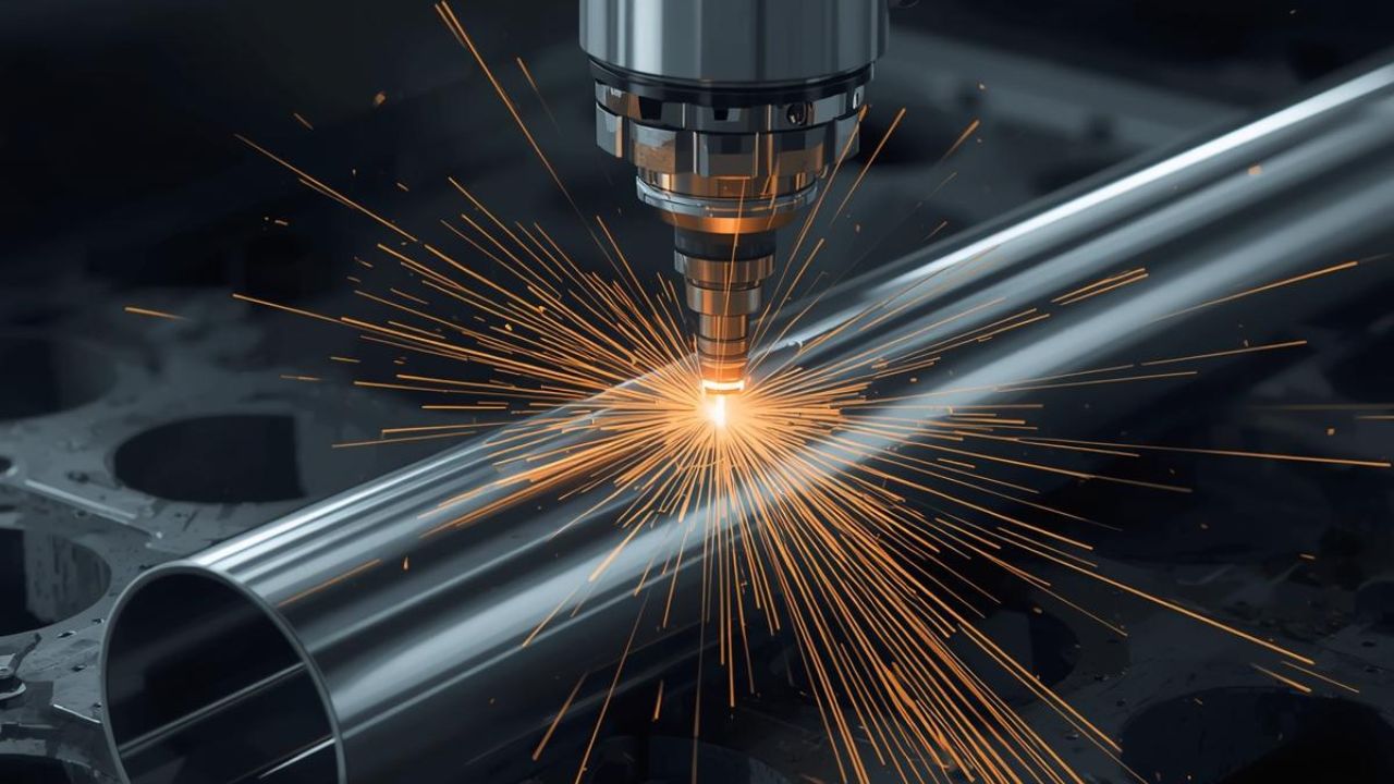
Material efficiency in tube laser cutting achieves scrap rates of 3-5% compared to 8-12% for traditional sawing and punching. Advanced laser systems with intelligent nesting software deliver material utilization rates of 92-95%, significantly reducing raw material consumption and manufacturing costs. The technology consolidates multiple fabrication steps into a single process, eliminating secondary operations while maintaining precision cutting tolerances.
Manufacturers adopting laser tube cutting report 15-20% raw material savings compared to conventional sawing. Narrow kerf widths, optimized nesting algorithms, and near-zero tail waste directly translate to measurable cost savings in laser cutting across production volumes, including reduced labor costs, shorter lead times, and improved part consistency.
Key Takeaways
- Tube laser cutting reduces scrap rates to 3-5% compared to 8-12% for traditional sawing methods, achieving 15-20% raw material savings through tighter tolerances and advanced nesting
- Process consolidation eliminates secondary operations like deburring and drilling, cutting manufacturing costs by 30% and reducing processing time by up to 80% per part
- CNC tube bending replaces welded assemblies, removing leak-failure modes and reducing per-part costs from $500-$5,000 in prototypes to $3-$30 in high-volume production
- Robotic welding delivers 30-50% higher throughput with defect rates below 1% compared to 5-8% for manual welding, with typical payback periods of 8-24 months
- Single-source integrated manufacturing consolidates vendor handoffs into internal transfers, reducing lead times by 30-40%, and total landed costs by 12-20%
What Is Tube Laser Cutting and How Does It Improve Material Efficiency?
Tube laser cutting uses focused laser beams to cut complex geometries in tubular materials with minimal waste. The process achieves higher precision and repeatability than mechanical cutting while eliminating multiple secondary operations. Laser systems handle round, square, rectangular, and custom profile tubes in a single setup.
Material efficiency improvements stem from three factors: reduced kerf width, optimized part nesting, and elimination of trim allowances. Traditional sawing requires wide cutting paths and substantial trim lengths at each tube end. Laser cutting minimizes both while enabling tighter part spacing.
How Does Tube Laser Cutting Compare to Traditional Sawing and Drilling in Scrap Rates?
Traditional saw and punch operations generate scrap rates between 8-12% of total raw material. Tube laser cutting reduces this to 3-5% through precise cutting paths and optimized material utilization. Material utilization rates for conventional sawing typically reach only 78-82% of raw stock.
Advanced laser systems with co-edge cutting achieve material utilization rates of 92-95% on common tube profiles. Raw material savings of 15-20% result from narrow kerf widths and intelligent part placement. One Southeast Asian manufacturing operation documented 15% material cost savings after implementing tighter nesting protocols with zero-tail cutting technology.
What Role Does Nesting Software Play in Maximizing Material Yield?
Nesting software algorithms optimize part placement along tube lengths to minimize waste between components and at tube ends. ADAM Integrated Industries improved material utilization by up to 20% after switching to JETCAM nesting software on their Trumpf laser system. Smart nesting reduces waste by 15-20% through strategic part arrangement that shares cut lines between adjacent components.
Modern chuck and motion control systems enable tail waste of 30mm or less, with some configurations achieving true zero-tail cutting. This capability saves 5-10% material per tube in high-volume runs where small improvements compound across thousands of parts. Advanced nesting strategies calculate true yield percentages by dividing net part area by total raw material area consumed.
How Do Kerf Widths Differ Between Laser Cutting and Sawing Methods?
Laser cutting produces kerf widths between 0.010 and 0.020 inches, depending on material type and beam parameters. Saw blade kerfs measure 0.125 inches or wider, removing substantially more material with each cut. The narrower laser kerf enables tighter part spacing and reduces cumulative material loss across production runs.
Traditional saw operations discard 12-20 inches of scrap per cut to accommodate trim allowances and blade entry zones. Trumpf tube laser systems with optimized nesting software reduce this to less than 8 inches per cut. Flexible setup capabilities allow rapid transitions between different part geometries without changing tooling or recalibrating equipment.
Table 1: Material efficiency compares directly when scrap rates, utilization, and kerf width are placed side by side.
| Metric | Traditional Sawing | Tube Laser Cutting |
| Scrap rate | 8-12% | 3-5% |
| Material utilization | 78-82% | 92-95% |
| Kerf width | 0.125 in. or wider | 0.010-0.020 in. |
| Scrap per cut (trim allowance) | 12-20 in. | Under 8 in. |
| Raw material savings | Baseline | 15-20% |
How Does Tube Laser Cutting Reduce Costs Through Process Consolidation?
Process consolidation eliminates multiple manufacturing steps by completing cutting, drilling, and profiling operations in a single laser setup. Traditional workflows require separate sawing, drilling, milling, and deburring stations with handling time between each operation. Laser cutting produces finished parts that often require no secondary processing.
Manufacturing cost reductions of 30% are documented for tube connections processed entirely by laser compared to traditional multi-step workflows. Processing time drops by up to 80% when conventional 150-minute fabrication sequences compress to 25-minute laser cycles, reducing both direct labor costs and work-in-process inventory.
What Cost Savings Result from Eliminating Secondary Operations Like Deburring?
LCSI documented approximately $100,000 per year in labor cost savings by eliminating grinding and deburring operations. Laser-cut edges typically require minimal or no deburring compared to saw-cut surfaces that need extensive finishing. When deburring remains necessary, it adds $0.50-$2.00 per cut part to production costs.
Aggregate production costs decrease by 26% through consolidated laser processing compared to fragmented traditional workflows. Material costs drop 20% through improved utilization while labor expenses decline by up to 40% from eliminated handling and secondary operations. Tube laser cutting services deliver these benefits across prototype and production volumes.
How Does Lead Time Benefit from Single-Setup Laser Processing?
Single-setup laser processing reduces lead times by up to 52% compared to multi-station traditional fabrication. Processing time reductions of up to 80% result from eliminating transfer time between sawing, drilling, and finishing operations. One documented case reduced fabrication time from 150 minutes to 25 minutes, achieving an 83% cycle time improvement.
Labor expense reductions reach up to 40% when operators oversee automated laser cutting rather than manually feeding multiple machines. Parts flow directly from laser cutting to assembly without intermediate inspection or deburring queues, reducing both touch time and queue time in production schedules.
What Are the Cost and Efficiency Advantages of Tube Forming Services?
Tube forming services combine bending, cutting, and end-forming operations to create complex tubular assemblies from single-piece tube stock. CNC tube bending eliminates welded joints between multiple straight sections, removing leak-failure modes and inspection requirements. Single-piece bent assemblies reduce part counts, inventory complexity, and assembly labor compared to multi-component welded structures.
Cost advantages scale dramatically with production volume as tooling investments amortize across larger quantities. Prototype tube forming costs $500-$5,000 per part while high-volume production reduces per-part costs to $3-$30. Eliminating fittings and welded joints from tube assemblies removes substantial cost drivers where skilled welding labor and inspection documentation escalate project expenses.
How Does CNC Tube Bending Compare to Welded Multi-Piece Assemblies in Cost Drivers?
Welded pipe systems require sequential cutting, alignment, welding, finishing, and inspection steps for each joint. Each welded joint introduces both labor costs and failure variables that compound quality risks throughout the structure. Welded sections carry more failure modes than bent tubes because cut quality and weld quality must both meet specifications.
Cycle time reductions of 60-80% are typical when transitioning from manual bending to CNC automated systems. Removing welds and joints eliminates documented leak-failure modes in complex assemblies, particularly for fluid-handling and high-pressure applications. Consistent repeatability in CNC bending maintains tight tolerances across production runs without manual adjustment.
How Do Cycle Time and Labor Costs Vary by Production Volume Tier?
Prototype tube forming operations cost $500-$5,000 per part as tooling development and setup time distribute across limited quantities. Low-volume production with soft tooling costs $3,000-$12,000 for tooling investment with 3-5 week lead times. High-volume production with hard tooling reduces per-part costs to $3-$30 once tooling investments reach full amortization.
Hard tooling break-even volumes occur near 1,875 units where cumulative per-part savings offset higher initial tooling costs. Per-part cost drops exceed 99% from prototype to high-volume production as non-recurring engineering expenses amortize. Typical cycle time improvements of 30-50% occur as processes refine and automation increases.
Table 2: Per-part costs drop sharply once tooling investment is spread across a larger production run.
| Production Tier | Tooling Investment | Per-Part Cost | Lead Time |
| Prototype | Minimal, part-specific setup | $500-$5,000 | Short-run, built per job |
| Low-volume (soft tooling) | $3,000-$12,000 | Declines as volume grows | 3-5 weeks |
| High-volume (hard tooling) | Amortized above ~1,875 units | $3-$30 | Fastest per-part turnaround |
What Are the Tooling Changeover Times and Setup Costs for Different Bending Methods?
Hydraulic tube benders require approximately 90 minutes to fit tooling and configure machines per part geometry change. Tubecraft documented up to 12 hours per week of lost production time with eight tool changeovers on hydraulic equipment. All-electric tube benders reduce setup time to approximately 20 minutes per changeover, less than one-quarter of hydraulic system requirements.
All-electric bending systems reclaim at least 9 hours per week of production capacity previously lost to hydraulic changeovers. New-part setup on modern all-electric benders completes in 30 minutes or less without manual hand-tool adjustments. Computer-programmed setup sequences eliminate trial-part waste and operator skill variables that affect hydraulic system changeover consistency.
How Does Automation Enhance Tube Assembly Fabrication Efficiency?
Automation increases tube assembly throughput through higher arc-on time, consistent process parameters, and reduced operator variability. Robotic welding cells maintain production speeds across shifts without fatigue-related quality degradation. Automated systems achieve 60-95% arc-on time compared to 15-35% for manual welding operations.
Throughput gains of 30-50% result from robotic welding’s ability to maintain consistent travel speeds and eliminate non-productive time. One fabrication shop reduced weld time from 45 minutes per part to 15 minutes per part, achieving 3× throughput improvement. Robotic welding systems deliver consistent quality while freeing skilled operators for higher-value tasks.
What Throughput and Consistency Gains Do Robotic Welding Offer Compared to Manual Methods?
Manual welding achieves arc-on time of 15-35% during production shifts due to setup, positioning, and inspection activities. Robotic welding systems maintain arc-on time of 60-95% by eliminating operator fatigue and optimizing motion paths. Robotic throughput gains reach 30-50% compared to manual operations through consistent execution.
Small fabrication shops document manual weld times of approximately 45 minutes per part for typical assemblies. The same operations complete in approximately 15 minutes per part with robotic welding cells, delivering 3× throughput improvement. Robotic travel-speed consistency maintains ±2% tolerance across shifts and production batches without operator-dependent variation.
How Does Robotic Welding Impact Defect and Rework Rates?
Manual welding operations experience defect rates of 5-8% under typical production conditions. Robotic welding systems reduce defect rates to less than 1% through precise parameter control and consistent execution. Manual rework and scrap rates range from 5-10% while robotic systems maintain rework rates of 0.5-3%.
Robotic consistency eliminates operator fatigue and skill variation that contribute to manual welding defects. Manual welding operations waste approximately 60% more wire than robotic systems through inconsistent technique and excessive spatter. Midmark documented a 10% reduction in weld wire consumption, saving $1,400 annually, plus a 20% reduction in grinding labor worth $50,000 annually.
What Is the Typical Payback Period for Investing in Robotic Welding Cells?
Midmark achieved approximately an 18-month payback on their robotic welding cell investment through combined material and labor savings. Industry payback periods for robotic welding cells typically range from 8-24 months depending on production volume and labor rates. Midmark’s installation saved $1,400 per year on weld wire and $50,000 per year on grinding labor.
Manual welding wire waste exceeds robotic consumption by approximately 60% due to inconsistent technique. Robotic systems reduce grinding requirements by 20% through consistent bead placement and reduced spatter. Equipment investments amortize quickly in high-volume operations where consistent quality and throughput advantages compound across thousands of parts.
What Lead Time Benefits Arise from Integrated Single-Source Manufacturing?
Integrated single-source manufacturing converts inter-vendor handoffs into internal transfers, eliminating receiving queues and redundant inspections. Traditional fabrication workflows route parts through separate vendors for cutting, forming, welding, and finishing, with shipping delays between each step. Each vendor transition introduces lead time, receiving inspection, and potential rework cycles that compound total project duration.
Domestic vertically-integrated laser operations reduce lead times by 30-40% compared to fragmented multi-vendor sourcing. Total landed costs decrease 12-20% through eliminated shipping, reduced handling, and consolidated quality control. Integrated manufacturing solutions maintain engineering continuity from prototype through production without vendor transitions.
How Does Vendor Consolidation Shorten Fabrication and Assembly Timelines?
Vendor consolidation reduces lead times by 30-40% through elimination of shipping delays and receiving queues between process steps. Total landed costs decrease 12-20% when domestic vertically-integrated facilities handle complete workflows internally. Traditional fabrication requires parts to route through fabrication, shipping, receiving, inspection, then forming vendor, then welding vendor, with cycles repeated at each transition.
Integrated single-source workflows process parts through design, cutting, bending, welding, and inspection, with all transfers occurring within one facility. Each vendor handoff introduces lead time, receiving queue, and quality inspection before work resumes. Single-source manufacturers eliminate these gaps while maintaining engineering knowledge continuity from initial design through final production.
What Lessons Can Be Learned from Cross-Industry Single-Source Lead Time Studies?
Cross-industry research in biopharmaceutical manufacturing demonstrates single-source contracting enables phase overlap that multi-vendor arrangements cannot achieve. Two-vendor cases document mean phase lengths of 10.4 months for drug substance plus 7.7 months for drug product, totaling 18.1 months with limited overlap capability. Single-source contractors compress timelines by overlapping phases that sequential multi-vendor arrangements must execute separately.
The same engineering team retains institutional knowledge from prototype through scale-up when projects remain with single-source partners. Vendor transitions at volume thresholds create requalification risks and knowledge transfer gaps that extend timelines. Manufacturing knowledge accumulated during prototype development applies directly to production ramp when the same team executes both phases.
How Does In-House Material Sourcing Improve Inventory and Supply Chain Efficiency?
In-house material inventory eliminates order lead times for common materials and protects production schedules during supply disruptions. Metal Fabrication Professionals maintains approximately $2 million of steel inventory in their 250,000-square-foot facility. Standard steel order lead times span 2-3 days minimum, with next-day delivery representing the fastest possible replenishment.
Strategic material stocking reduces schedule risk in custom precision fabrication where specific materials, finishes, and documentation must meet pre-qualified specifications. During supply constraints, MFP held 300+ sheets on hand while market lead times for 7-gauge material extended to 10-14 days. Comprehensive laser tube cutting capabilities require coordinated material availability to maintain production flow.
What Are the Advantages of Maintaining On-Hand Steel Inventory?
On-hand steel inventory eliminates 2-3 day minimum order lead times that affect production scheduling for custom projects. MFP’s $2 million inventory investment enables same-day material availability compared to multi-day procurement cycles. During one supply squeeze, 7-gauge material lead times reached 10-14 days while MFP maintained 300+ sheets in facility stock.
Carrying costs for strategic inventory on high-runner materials typically remain far less than the lead time reduction value. Material availability enables fabricators to commit to shorter customer lead times without supply-chain risk exposure. Strict just-in-time approaches create schedule risk in custom precision fabrication where specific materials require pre-qualification.
How Do Different Inventory Strategies Affect Lead Time and Scheduling?
Blanket orders and long-term forecasting enable fabricators to plan production around expected demand rather than reacting per purchase order. Suppliers with integrated machining and fabrication capabilities receive increasing preference from OEMs seeking supply chain resilience. Strategic stock for frequently ordered materials reduces effective lead times without excessive working capital investment.
Strict just-in-time inventory can create schedule risk in custom precision fabrication requiring specific materials, finishes, or documentation. Pre-qualified materials must remain available when production schedules demand immediate availability. Inventory strategies should match program requirements and customer lead-time expectations rather than following blanket philosophical approaches.
How Does Software Optimization Complement Physical Tube Fabrication Processes?
Software optimization maximizes material yield through intelligent nesting algorithms that minimize waste between parts and at tube ends. ADAM Integrated Industries achieved material utilization improvements approaching 20% after implementing JETCAM nesting software on their Trumpf laser system. Co-edge cutting represents an advanced nesting technique that shares cut lines between adjacent parts to reduce total kerf loss.
True yield percentage calculations divide net part area by total raw material area to quantify nesting efficiency improvements. Capacity-based scheduling software reduces lead times 30-50% within 3-6 months through optimized work release without capacity or speed changes. Software complements physical fabrication equipment by maximizing utilization of existing machine capabilities.
What Nesting Software Features Drive Material Utilization and Waste Reduction?
Co-edge cutting shares cut lines between adjacent parts to eliminate redundant kerf width and maximize material utilization. ADAM Integrated Industries, a contract manufacturer using a Trumpf L2503e laser with FastCat Plasma, switched to JETCAM nesting software for optimization. Nesting waste reduction via smart software typically achieves 15-20% improvement through optimized part placement.
True yield percentage equals net part area divided by raw material area consumed in the cutting process. Advanced nesting algorithms evaluate different configurations including single-length versus mixed-length bar stock to optimize yield. Remnant tracking and batch nesting represent primary levers for yield improvement when processing multiple concurrent orders.
How Can Scheduling Software Contribute to Lead Time Reduction?
Capacity-based scheduling software achieves lead time reductions of 30-50% within 3-6 months of implementation. Work release optimization matches job sequences to available capacity without increasing machine speeds or adding equipment. Strategic stock management for high-runner materials integrates with scheduling systems to ensure material availability aligns with production timing.
Software-driven scheduling eliminates queue-time waste by releasing work to production cells based on actual capacity rather than arbitrary calendar dates. For integrated precision bending cutting services handling multiple operations in sequence, tighter production control reduces work-in-process inventory and shortens the time between order receipt and finished goods delivery. Scheduling optimization delivers measurable lead time improvements without capital investment.
Integrating Tube Laser Cutting for Maximum Efficiency and Cost Reduction
Waste reduction laser cutting technology delivers measurable improvements in material utilization, manufacturing costs, and production lead times across diverse applications. Material efficiency gains of 15-20% combine with 30% manufacturing cost reductions to generate rapid return on investment. Process consolidation eliminates secondary operations while robotic automation increases throughput by 30-50% with defect rates below 1%.
Single-source integrated manufacturing partners consolidate vendor handoffs into internal transfers, reducing lead times by 30-40% and total costs by 12-20%. Strategic material inventory management and software optimization maximize existing equipment capabilities without additional capital investment. CRD MFG, Inc. combines laser tube cutting, CNC bending, and robotic welding in a 22,500-square-foot facility to deliver complete tube assemblies from raw stock to finished products.
Partner with CRD MFG, Inc. for Tube Laser Cutting and Tube Forming
CRD MFG, Inc. combines laser tube cutting, CNC tube bending, and robotic welding in a 22,500-square-foot facility in Placentia, California. Each project is assigned a single dedicated project manager who tracks material sourcing, cutting, forming, and inspection from quote to delivery, so your team gets direct answers instead of departmental handoffs. Call CRD MFG, Inc. at (714) 871-3300 or request a quote to discuss material efficiency and cost targets for your next tube fabrication project.
Frequently Asked Questions About Tube Laser Cutting and Material Efficiency
Q1. How much material can tube laser cutting save compared to sawing?
Tube laser cutting typically reduces scrap rates from the 8-12% range common with sawing and punching down to 3-5%. Advanced nesting software raises material utilization to 92-95%, compared with 78-82% for conventional sawing. Manufacturers switching to laser cutting report raw material savings of 15-20%, driven by narrower kerf widths and tighter part spacing.
Q2. Does tube laser cutting eliminate the need for deburring?
Laser-cut edges usually need little or no deburring, unlike saw-cut surfaces that often require extensive finishing. When deburring is still needed, it typically adds $0.50-$2.00 per part rather than a full secondary operation. This is one reason process consolidation through laser cutting can lower total manufacturing costs by up to 30%.
Q3. What is the typical payback period for robotic welding equipment?
Payback periods for robotic welding cells generally range from 8-24 months, depending on production volume and labor rates. Robotic welding also raises arc-on time to 60-95%, compared with 15-35% for manual welding, while cutting defect rates below 1%. Documented cases show additional annual savings on weld wire and grinding labor once the equipment is in place.
Q4. How does production volume affect tube forming costs?
Prototype tube forming runs $500-$5,000 per part because tooling and setup costs spread across a small quantity. Low-volume production with soft tooling costs $3,000-$12,000 in tooling investment with 3-5 week lead times. High-volume production with hard tooling reduces per-part costs to $3-$30 once volumes pass roughly 1,875 units and tooling investment fully amortizes.
Q5. Can CRD MFG, Inc. handle laser cutting and CNC tube bending under one roof?
Yes. CRD MFG, Inc. performs laser tube cutting, CNC tube bending, robotic welding, and assembly in the same Placentia, California facility, supported by in-house material sourcing and a Faro Arm inspection system. Keeping these processes internal removes the shipping delays and receiving queues that come with multi-vendor workflows. Contact CRD MFG, Inc. at (714) 871-3300 or crdmfg.com/contact to review your project scope with a project manager.
